Array-type ultrasonic probe and ultrasonic diagnostic apparatus
a technology of ultrasonic probes and diagnostic equipment, applied in diagnostics, instruments, medical science, etc., can solve the problems of low reliability of ultrasonic probes, thermal expansion coefficient between epoxy resins and resins, and materials that do not meet all the various properties required
- Summary
- Abstract
- Description
- Claims
- Application Information
AI Technical Summary
Problems solved by technology
Method used
Image
Examples
examples 1
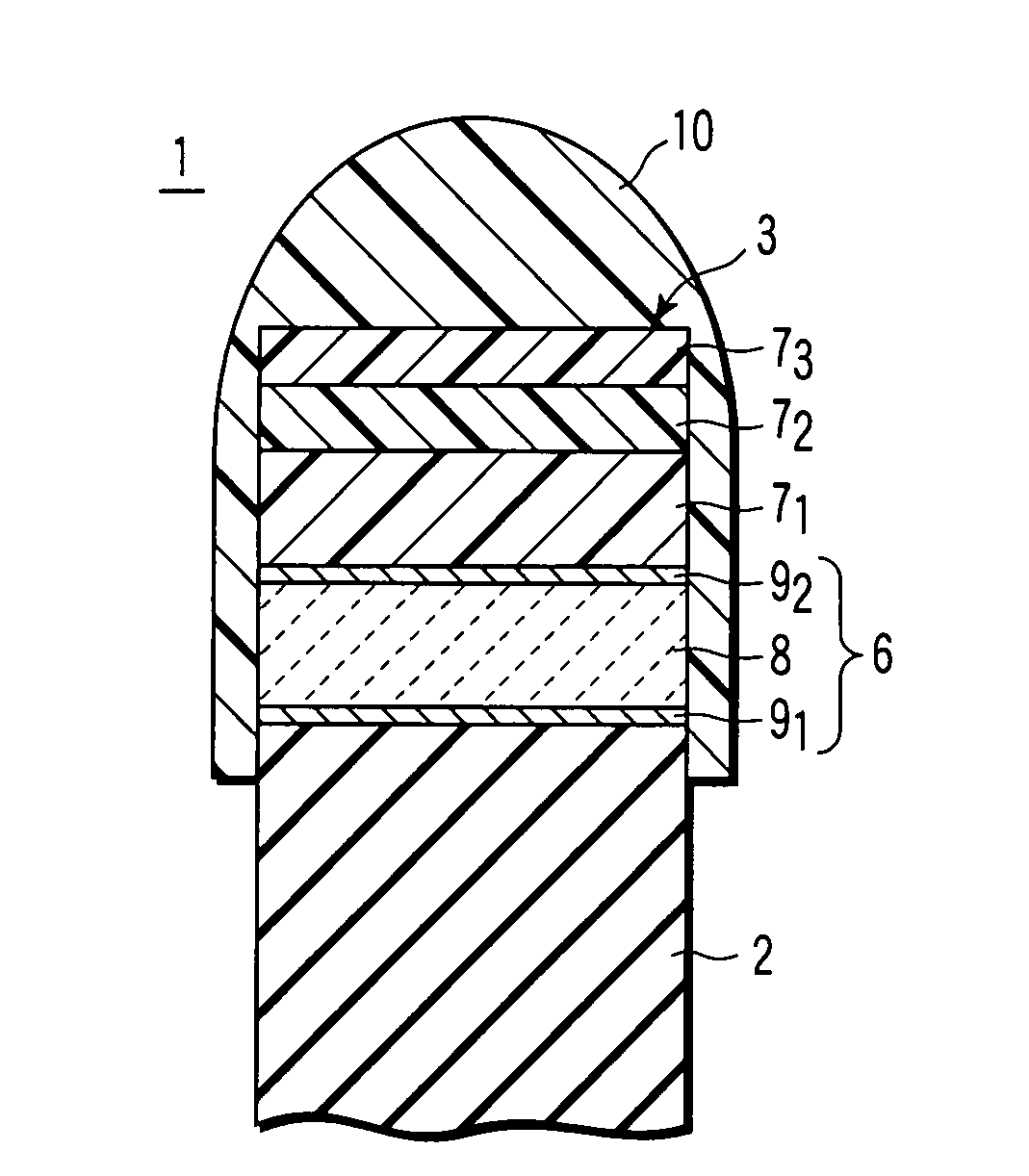
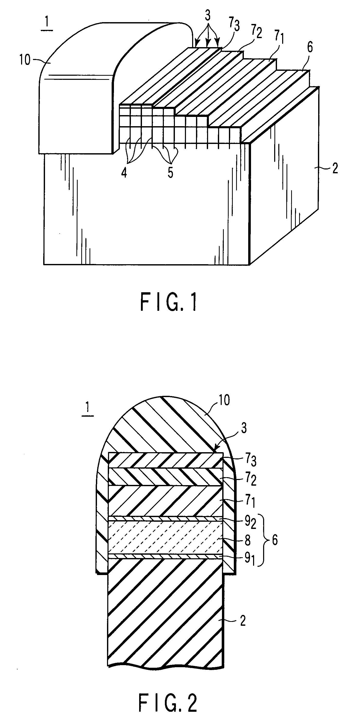
[0074]Two-part silicone resins of SCR 1011 resin A and SCR 1011 resin B, available from Shin-Etsu Chemical Co. Ltd., were weighed accurately at a weight ratio of 1:1. Then, the silicone resin-containing mixture was put in a polyethylene cup and uniformly mixed for 3 minutes while stirring the mixture within a rotary mixer. The liquid resin mixture was defoamed for 10 minutes in a vacuum container, followed by putting the defoamed resin mixture in a container made of Teflon (registered trademark). In the next step, the defoamed resin mixture was subjected to a preliminary curing at 85° C. for one hour, followed by further curing the resin at 125° C. for 2 hours so as to manufacture a raw material of the third acoustic matching layer.
[0075]A thermogravimetric analyzer (TG) and a differential thermal analyzer (DTA) were applied to the cured material of the silicone resin-containing mixture obtained in Example 1 (raw material of the third acoustic matching layer) under the conditions gi...
examples 2 to 9
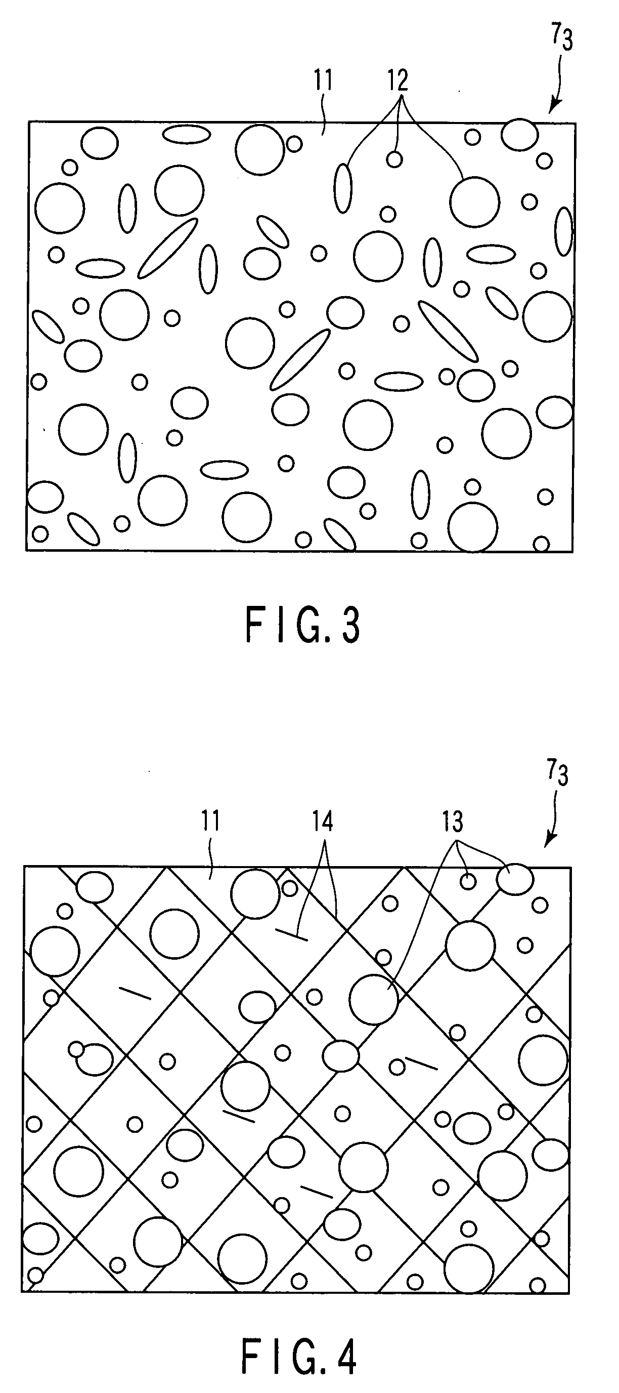
[0088]Raw materials for the third acoustic matching layers were manufactured as in Example 1 by using SCR 1012, SCR 1011 and SCR 1004, available from Shin-Etsu Chemical Co. Ltd., as two-part silicone resins (silicone resin-based mixture) as shown in Table 1. A prescribed filler was dispersed in some of these raw materials of the third acoustic matching layers. Used as the fillers were silicone rubber particles having an average particle diameter of 3 μm, epoxy resin particles having an average particle diameter of 10 μm, a powdery silicon oxide having an average particle diameter of 20 nm, a powdery zinc oxide having an average particle diameter of 30 nm, a powdery titanium oxide having an average particle diameter of 50 nm, a fibrous glass having an average diameter of 5 μm and an average length of 100 μm, and a fibrous carbon having an average diameter of 7 μm and an average length of 100 μm.
TABLE 1Composition of third or fourth acoustic matching layerOrganicPowderyFibrousfillerin...
examples 10 , 11
EXAMPLES 10, 11 AND COMPARATIVE EXAMPLES 1 TO 6
[0089]The raw materials of the third acoustic matching layers were manufactured as in Example 1 by using as the base resin, i.e., as the two-part silicone resin (silicone resin-based mixture), each of SCR 1011 and SCR 1012, each available from Shin-Etsu Chemical Co. Ltd., a polyurethane rubber, a silicone rubber, an epoxy resin, polyethylene, a high hardness silicone resin available from Shin-Etsu Chemical Co. Ltd under the trade name of KER 2500, and a high hardness silicone resin available from MOMENTIVE PERFORAMANCE MATERIALS Inc. under the trade name of IVSM 4500 as shown in Table 2. A prescribed filler selected from the group consisting of silicone rubber particles having an average particle diameter of 3 μm, a powdery silicon oxide having an average particle diameter of 20 nm, a powdery alumina having an average particle diameter of 100 nm and a fibrous silicon oxide having an average diameter of 5 μm and an average length of 100 ...
PUM
 Abstract
Description
Claims
Application Information
 - R&D
- Intellectual Property
- Life Sciences
- Materials
- Tech Scout
- Unparalleled Data Quality
- Higher Quality Content
- 60% Fewer Hallucinations
Browse by: Latest US Patents, China's latest patents, Technical Efficacy Thesaurus, Application Domain, Technology Topic, Popular Technical Reports.
© 2025 PatSnap. All rights reserved.Legal|Privacy policy|Modern Slavery Act Transparency Statement|Sitemap|About US| Contact US: help@patsnap.com


