Exposure apparatus and method
- Summary
- Abstract
- Description
- Claims
- Application Information
AI Technical Summary
Benefits of technology
Problems solved by technology
Method used
Image

Examples
first embodiment
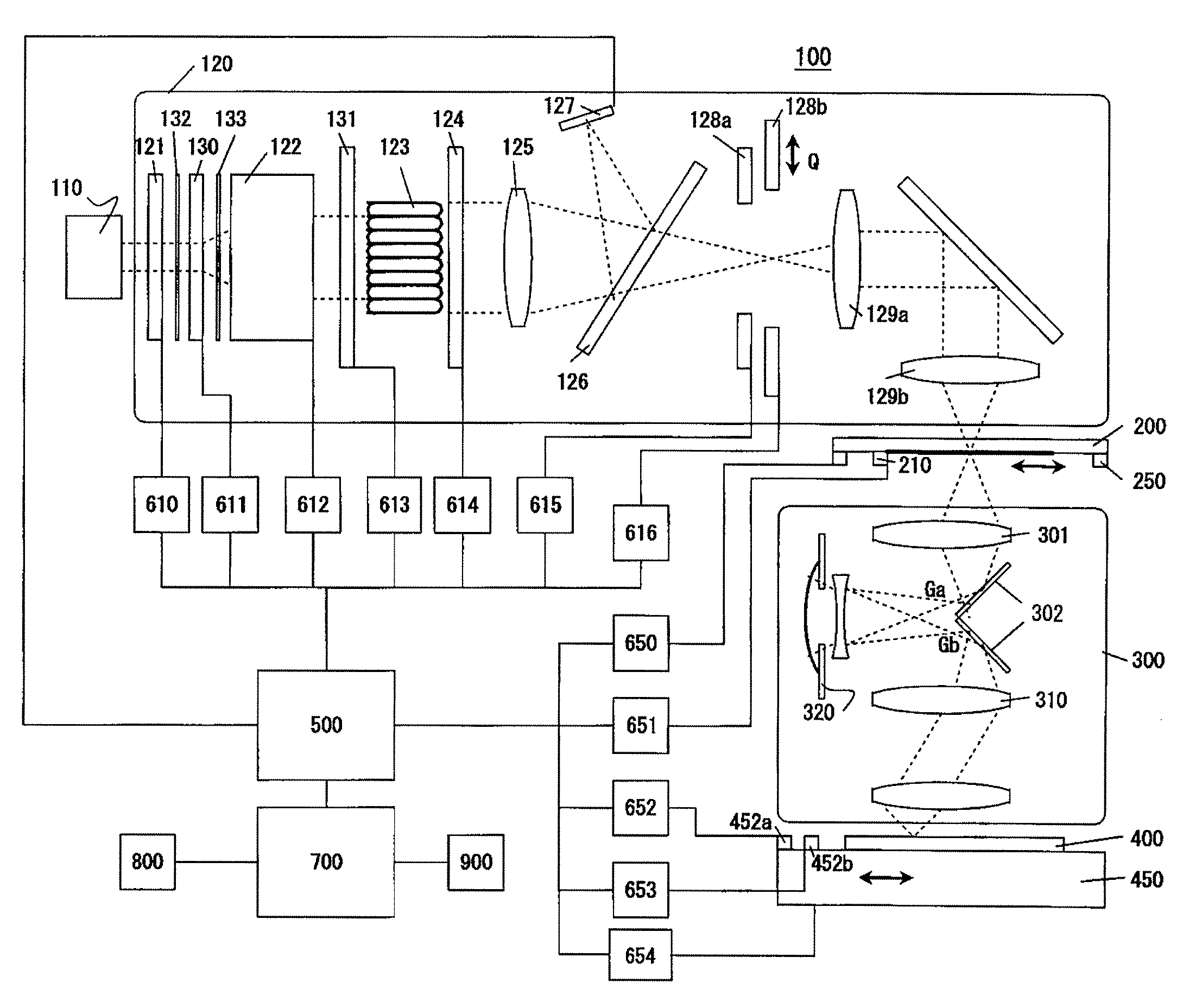
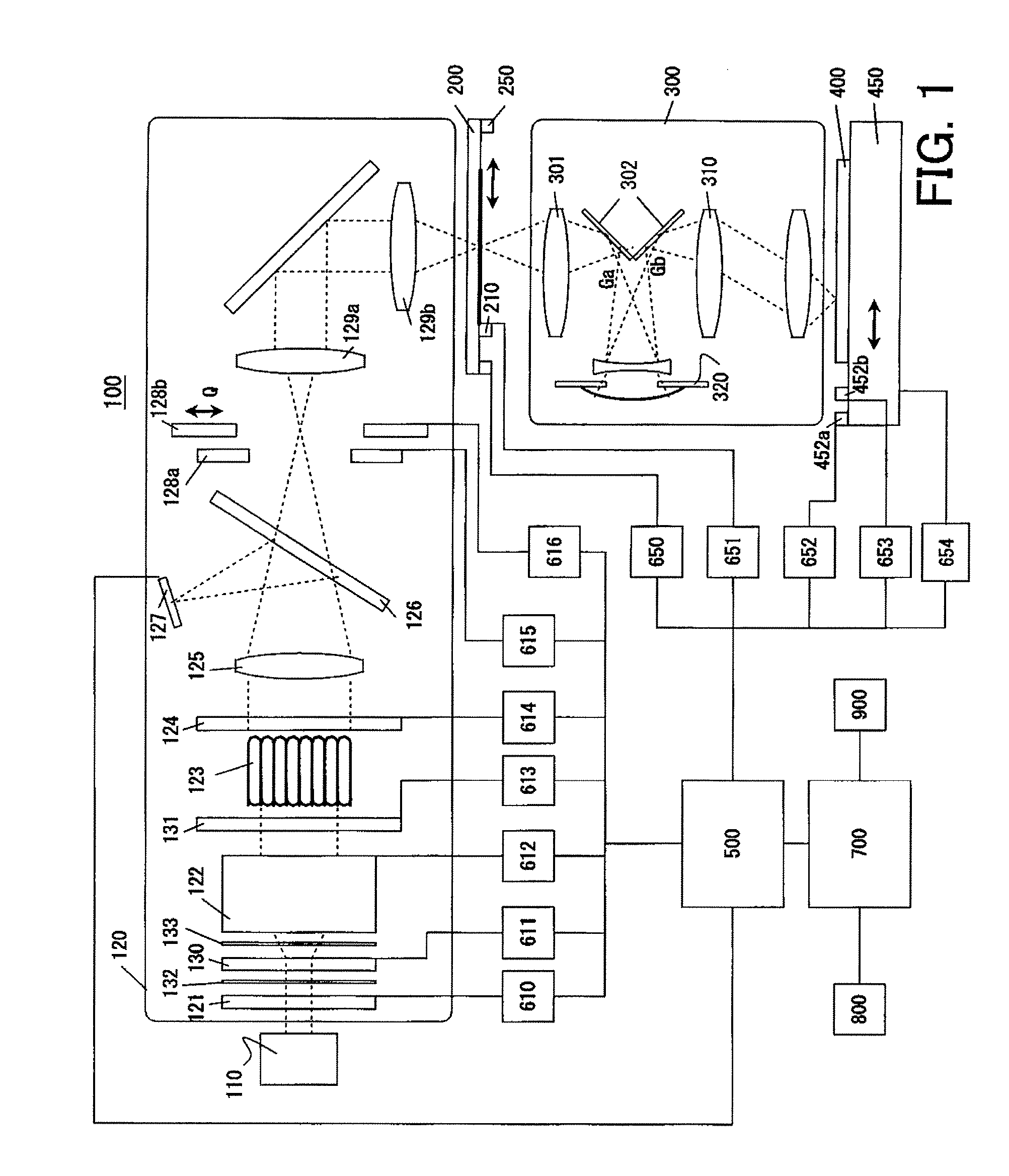
[0047] A description will now be given of an exposure apparatus 100 according to one aspect of the present invention. Here, FIG. 1 is a schematic block diagram of the exposure apparatus 100. The exposure apparatus 100 is a projection exposure apparatus that exposes a pattern of a reticle 200 onto a plate 400 in a step-and-scan manner, and is suitable for the lithography process for a resolution below a sub-micron or quarter-micron. The exposure apparatus 100 includes, as shown in FIG. 1, an illumination apparatus, a projection optical system 300, a controller 500, a imaging simulator 700, and memories 800 and 900.
[0048] The illumination apparatus illuminates the reticle 200, on which a circuit pattern to be transferred is formed, and includes a light source 110 and an illumination optical system 120.
[0049] The light source 110 uses, for example, a laser. The laser can use an ArF excimer laser with a wavelength of approximately 193 [nm], a KrF excimer laser with a wavelength of app...
second embodiment
[0094] This embodiment will discuss a correction method when a polarization property differs for each image height. The exposure apparatus 100 has the same structure as that of the first embodiment. The polarization information may use the Stokes parameter and Jones vector. But the degree of polarization, which is a simple expression as one dimensional polarization information, is taken up as an example to explain. A solid line in FIG. 9 denotes an exposure slit area S, and a broken line denotes an area frome where the ray can pass through the pupil in the projection optical system 300. As shown in FIG. 9, when the photodetector 210 measures the light at plural measuring points that align in the longitudinal direction in the slit S, the degree of polarization to the pupil can be expressed as a two-dimensional map ROPi(u, v) for each image height. The slit longitudinal direction is a perpendicular direction to the paper plane on the reticle in FIG. 1.
[0095] While the first embodimen...
third embodiment
[0107] This embodiment is different from the first embodiment in that this embodiment gets the polarization information both near the reticle plane and near the plate plane. Two pieces of polarization information are expressed as follows, where J1ol and J2ol are polarization information near the wafer plane, J1il and J2il are polarization information near the reticle plane, and UL(uol, vol) is a polarization information component of a projection optical system: (J1o l(uol,vol)ⅇⅈφ1ol(uol,vol)J2o l(uol,vol)ⅇⅈφ2ol(uol,vol))=UL(uol,vol)(J1i l(uil,vil)ⅇⅈφ1il(uil,vil)J2i l(uil,vil)ⅇⅈφ2il(uil,vil))[EQUATION 6]
[0108] Equation 7 is met when the term relating to UL in Equation 6 is developed, where eiΦ(u, v) is a conventional aberration term, and T(u, v) is a conventional pupil amplitude transmittance. UL(u,v)=(J11(u,v)ⅇⅈφ11(u,v)J12(u,v)ⅇⅈφ12(u,v)J21(u,v)ⅇⅈφ21(u,v)J22(u,v)ⅇⅈφ22(u,v))=ⅇⅈφ(u,v)T(u,v)(J11′(u,v)J12′(u,v)ⅇⅈφ11(u,v)ⅇⅈφ12(u,v)J21′(...
PUM
 Abstract
Description
Claims
Application Information
 - R&D
- Intellectual Property
- Life Sciences
- Materials
- Tech Scout
- Unparalleled Data Quality
- Higher Quality Content
- 60% Fewer Hallucinations
Browse by: Latest US Patents, China's latest patents, Technical Efficacy Thesaurus, Application Domain, Technology Topic, Popular Technical Reports.
© 2025 PatSnap. All rights reserved.Legal|Privacy policy|Modern Slavery Act Transparency Statement|Sitemap|About US| Contact US: help@patsnap.com