Camera module

Inactive Publication Date: 2007-03-01
MITSUMI ELECTRIC CO LTD
View PDF2 Cites 37 Cited by
  • Summary
  • Abstract
  • Description
  • Claims
  • Application Information

AI Technical Summary

Benefits of technology

[0015] The present invention has been made in view of the above drawbacks. It is, therefore, an object of the present invention to provide a ca

Problems solved by technology

As a result, the housing space 133 cannot maintain a hermetically sealed state to prevent dust from being attached to surfaces of the image pickup device 15.
This period of time required for confirmation lowers a working efficiency of the operator.
Further, the impregnation of the resin adhesive is also affected by other factors such as a temperat

Method used


Image

  • Camera module
  • Camera module
  • Camera module

Examples


Example

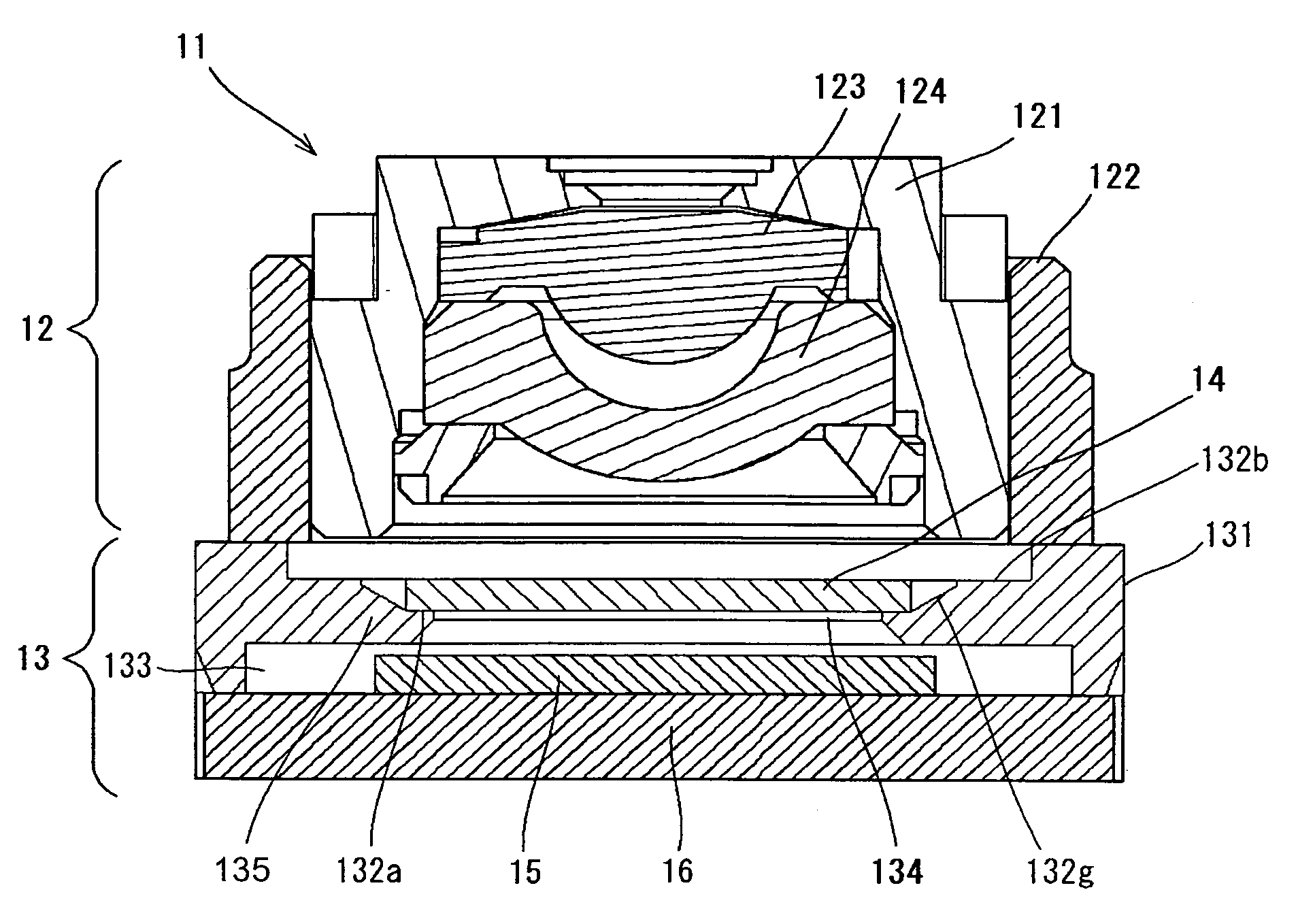
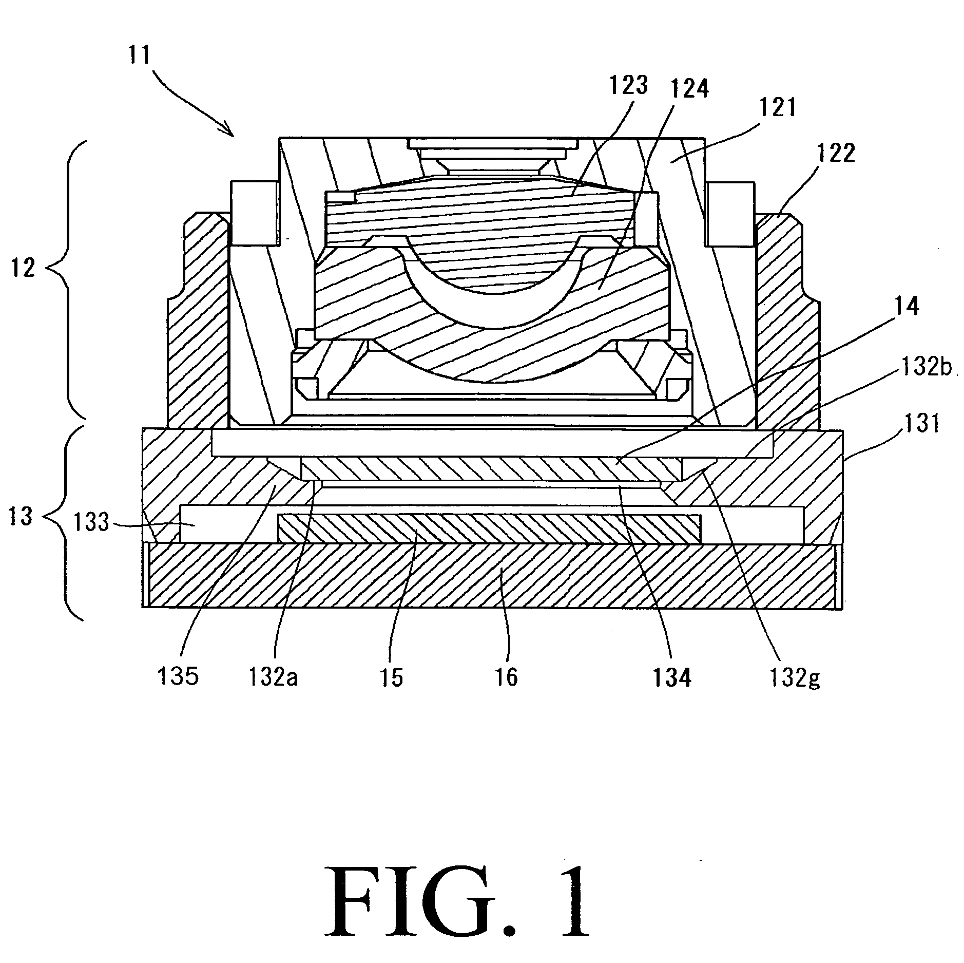
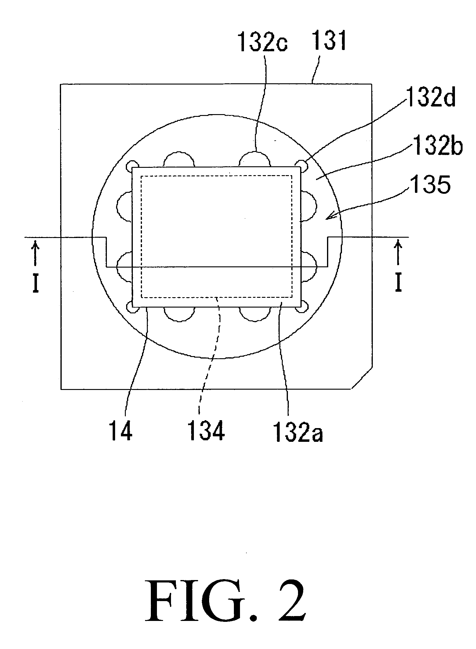
[0027] A camera module according to an embodiment of the present invention will be described below with reference to FIGS. 3 and 4. FIG. 3 is a cross-sectional view of a camera module 1 in an embodiment of the present invention. FIG. 4 is a plan view of a base 31 and an IR cut filter 4 in the camera module 1 in FIG. 3. FIG. 3 is a cross-section generally taken along a line III-III of FIG. 4. As shown in FIG. 3, the camera module 1 has a lens unit 2 and an image pickup portion 3 provided below the lens unit 2.

[0028] The lens unit 2 has a first lens 23, a second lens 24, a barrel 21 housing the first lens 23 and the second lens 24, and a lens holder 22 for rotatably supporting the barrel 21. When the lens holder 22 is rotated, the barrel 21 moves in a direction of an optical axis so as to control a focus of the camera module 1. For example, the first lens 23 and the second lens 24 are provided as an optical system in the camera module 1. However, the camera module 1 may have an optic...


PUM


Abstract

A camera module has a lens unit and an image pickup portion. The lens unit has at least one lens and a lens holder for holding the at least one lens. The image pickup portion is provided below the lens unit. The image pickup portion has a substrate, an image pickup device mounted on the substrate, a housing space for housing the image pickup device therein in a hermetically sealed state, and a base provided above the substrate. The base has an opening for introducing light passing through the at least one lens to the image pickup device in the housing space, a support portion located around the opening, and a recessed groove located around the support portion for holding a resin adhesive for bonding. The image pickup portion also has a filter having a peripheral portion bonded to an upper surface of the support portion so as to cover the opening of the base.

Description

[0001] This application claims priority to Japanese Patent Application No. 2005-252851 filed Aug. 31, 2005, which is hereby expressly incorporated by reference herein in its entirety. BACKGROUND OF THE INVENTION [0002] 1. Field of the Invention [0003] The present invention relates to a camera module, and more particularly to a relatively small camera module to be mounted on an electronic apparatus, such as, for example, a cellular phone. [0004] 2. Description of the Prior Art [0005] A relatively small camera module is mounted on an electronic apparatus, such as, for example, a cellular telephone. Such a camera module includes an image pickup device, such as, for example, a CMOS sensor or a CCD sensor. FIG. 1 illustrates a cross-sectional view of a conventional camera module 11, and FIG. 2 is a plan view illustrating a base 131 and an IR cut filter 14 in the conventional camera module 11. FIG. 1 is a cross-sectional view taken generally along a line I-I of FIG. 2. As shown in FIG. 1,...

Claims


Application Information

Patent Timeline
IPC IPC(8): G02B7/02
CPCH04N5/2254H04N23/55
Inventor SHIBATA, HISASHISATO, TOSHIHIKO
Owner MITSUMI ELECTRIC CO LTD
Why Eureka
Try Eureka