Circuit breaker tester including a pulse width modulation circuit

Active Publication Date: 2007-03-01
EATON INTELLIGENT POWER LIMITED
View PDF12 Cites 20 Cited by
  • Summary
  • Abstract
  • Description
  • Claims
  • Application Information

AI Technical Summary

Benefits of technology

[0013] Some of the load elements may have the same values of the nominal fixed impedance. The controller may further be structured to employ different ones of the load elements having one of the same values of the nominal fixed impedance for subsequent tests of the circuit breaker under test or of at least one different circuit breaker, in order to avoid overheating of the different ones of the load elements having one of the same values of the nominal fixed imped

Problems solved by technology

The job is made more difficult by the high density of these very small circuit breakers a

Method used


Image

  • Circuit breaker tester including a pulse width modulation circuit
  • Circuit breaker tester including a pulse width modulation circuit
  • Circuit breaker tester including a pulse width modulation circuit

Examples


example 1

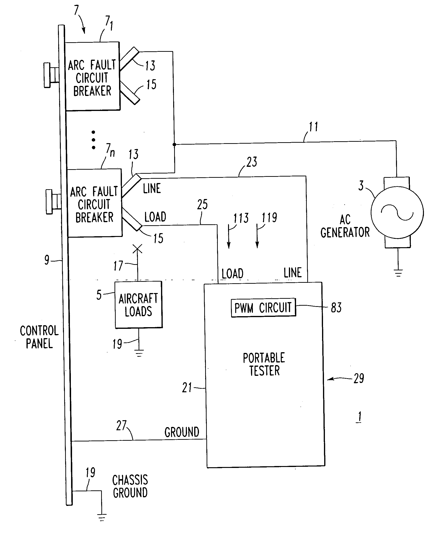
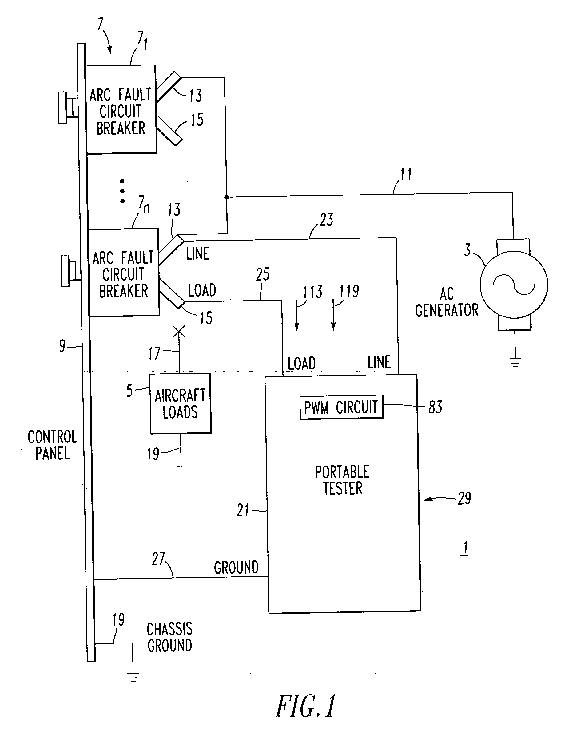
[0040] The tester 21 is preferably housed in a suitcase-like enclosure 29 (FIGS. 4 and 5) for portability. The enclosure 29 includes a base 31 and a cover 33 (which is removed in FIG. 5 for convenience of illustration).

example 2

[0041] The tester 21 is preferably structured to select and test one of a thermal test and an arc fault test for one of the circuit breakers 7 under test. As will be described, the tester 21 preferably tests both arc fault and non-arc fault circuit breakers on either AC or DC loads, in various current ranges and / or line voltage ranges, and in various types of tests.

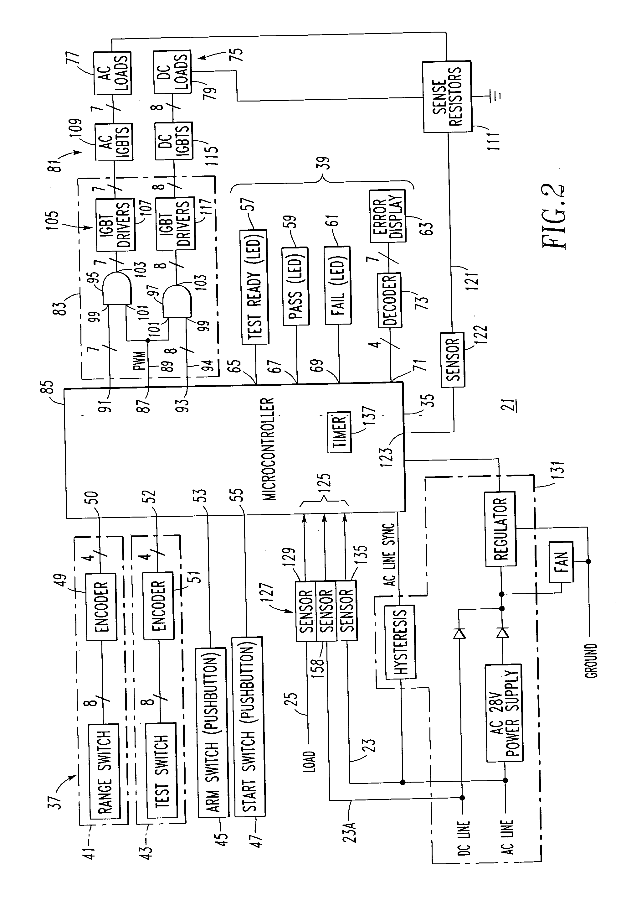
[0042] Referring to FIG. 2, the example tester 21 includes a suitable controller, such as, without limitation, a microcontroller (μC) 35, a plurality of user inputs 37 and a plurality of indicators 39. The user inputs 37 include a rotary range switch 41, a rotary test switch 43, an arm pushbutton 45 and a start pushbutton 47. A first encoder 49 of the range switch 41 encodes eight positions of the range switch to four inputs 50 of the μC 35, and a second encoder 51 of the test switch 43 encodes eight possible positions (only four positions are employed) of the test switch to four μC inputs 52. The arm pushbutton 45 and t...

example 3

[0051] Although FIG. 1 shows an AC generator 3, external AC power or DC power may be provided by any suitable external power source. For example, an AC or DC generator or power supply other than the example aircraft AC generator 3 may be employed. The example tester 21 includes a power supply circuit 131 (FIG. 2) structured to receive either an AC voltage from line lead 23 or a DC voltage from line lead 23A. A zero crossing detector (AC LINE SYNC) synchronizes turning on of the AC power IGBTs 109 with half cycles of the alternating current.


PUM


Abstract

A tester for testing a circuit breaker includes a plurality of load elements each having a nominal fixed impedance and an electronic switch associated with each load element. The electronic switch, when turned on, electrically connects a corresponding load element in series with a circuit breaker load terminal and in parallel with none or with a number of other load elements. A controller turns on a number of the electronic switches selected to draw through a corresponding number of the load elements a test current selected as a function of a designated rated current for the circuit breaker and sufficient to trip open the same. A pulse width modulation circuit cooperates with the controller and with the electronic switches. The pulse width modulation circuit provides a constant magnitude of the test current to accommodate variations of the nominal fixed impedance or variations of the voltage of the load terminal.

Description

BACKGROUND OF THE INVENTION [0001] 1. Field of the Invention [0002] This invention relates to equipment for testing in situ the trip functions of circuit breakers which may have a range of rated currents and / or line voltages. [0003] 2. Background Information [0004] Circuit breakers in some applications are tested periodically to assure reliability. This is particularly so in aircraft electrical systems. It is preferable that the circuit breakers be tested in their installed state. The job is made more difficult by the high density of these very small circuit breakers and the fact in any one aircraft system, the breakers can have a range of current ratings. Furthermore, aircraft circuit breakers are now being offered with multiple trip functions. [0005] U.S. Pat. No. 6,744,260 discloses a tester employing various power resistors for testing delayed trip and arc fault trip functions. A suitcase enclosure encloses the portable tester. A test selector switch includes one position for a ...

Claims


Application Information

Patent Timeline
IPC IPC(8): H02H3/00
CPCH02H1/0015G01R31/3277
Inventor MILLS, PATRICK W.GONYEA, KEVIN D.BENSHOFF, RICHARD G.LAWTON, JEFFREY C.ELLSWORTH, MAURICE R.
Owner EATON INTELLIGENT POWER LIMITED
Why Eureka
Try Eureka