Phase detector and related phase detecting method thereof

a phase detector and phase detection technology, applied in the direction of oscillator comparator circuits, angle demodulation by phase difference detection, electrical devices, etc., can solve problems such as continuous errors in the result of phase detection

Inactive Publication Date: 2007-03-01
MEDIATEK INC
View PDF4 Cites 7 Cited by
  • Summary
  • Abstract
  • Description
  • Claims
  • Application Information

AI Technical Summary

Benefits of technology

[0008] According to another exemplary embodiment, a phase detecting method for detecting a phase difference between a first signal and a second signal is disclosed. The phase detecting method comprises: outputting a pulse having a period in which a logic level of the first signal is different from a logic level of the second signal; outputting an detection signal to identify a phase leading / lagging relationship between the first signal and the second signal; and combining the pulse and the detection signal to output a result signal, wherein the result signal comprises difference and leading / lagging information between the first and the second signal. The disclosed phase detector can detect the phase difference between signals with fewer errors.

Problems solved by technology

However, a glitch of an input signal may trigger a false state transition, leading to continuous errors of the result of phase detection.

Method used


Image

  • Phase detector and related phase detecting method thereof
  • Phase detector and related phase detecting method thereof
  • Phase detector and related phase detecting method thereof

Examples


first embodiment

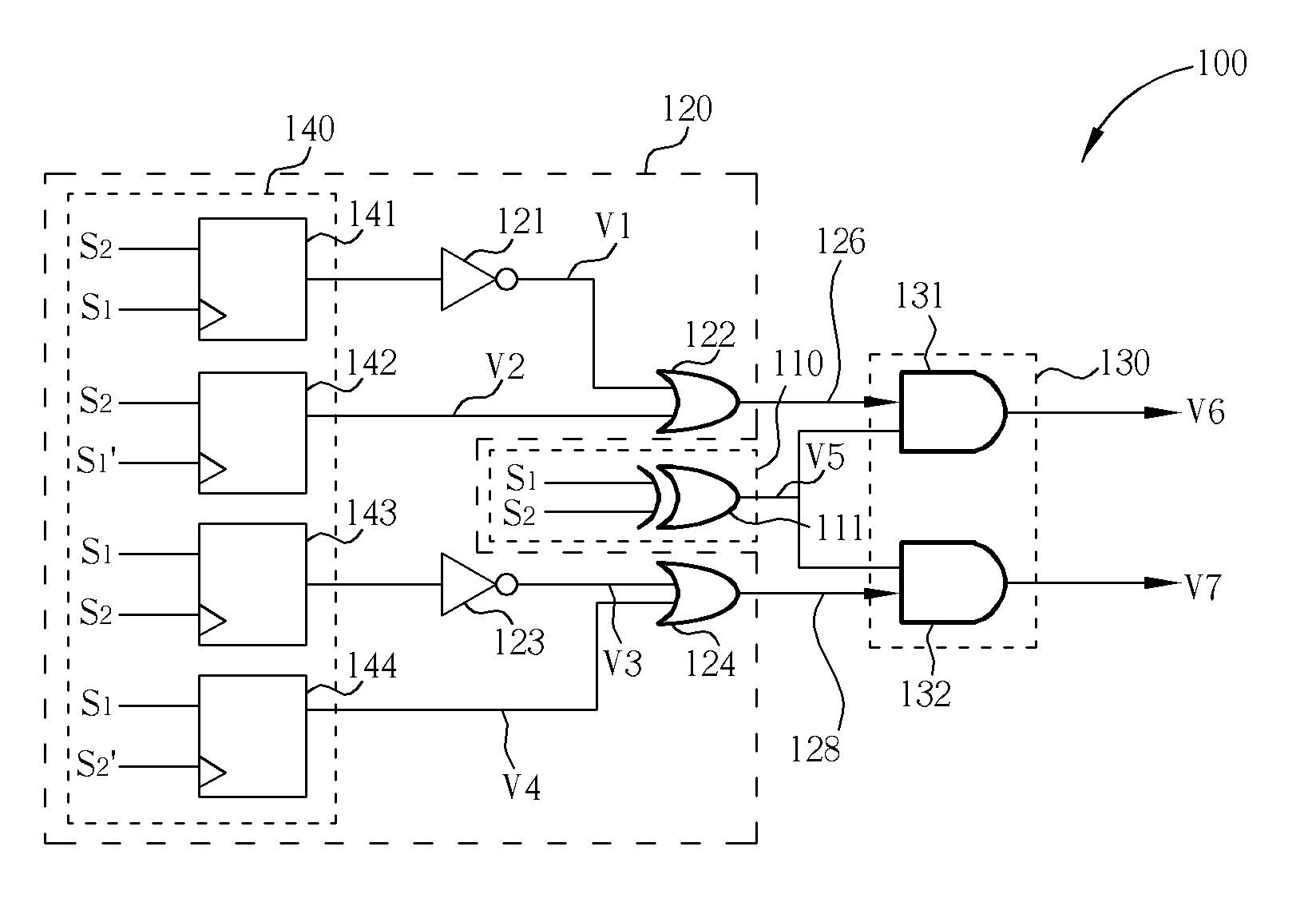
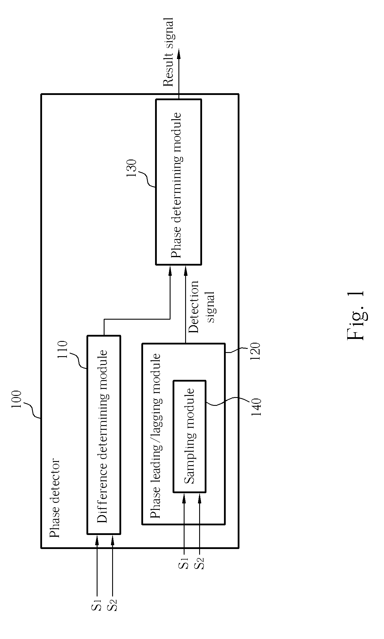
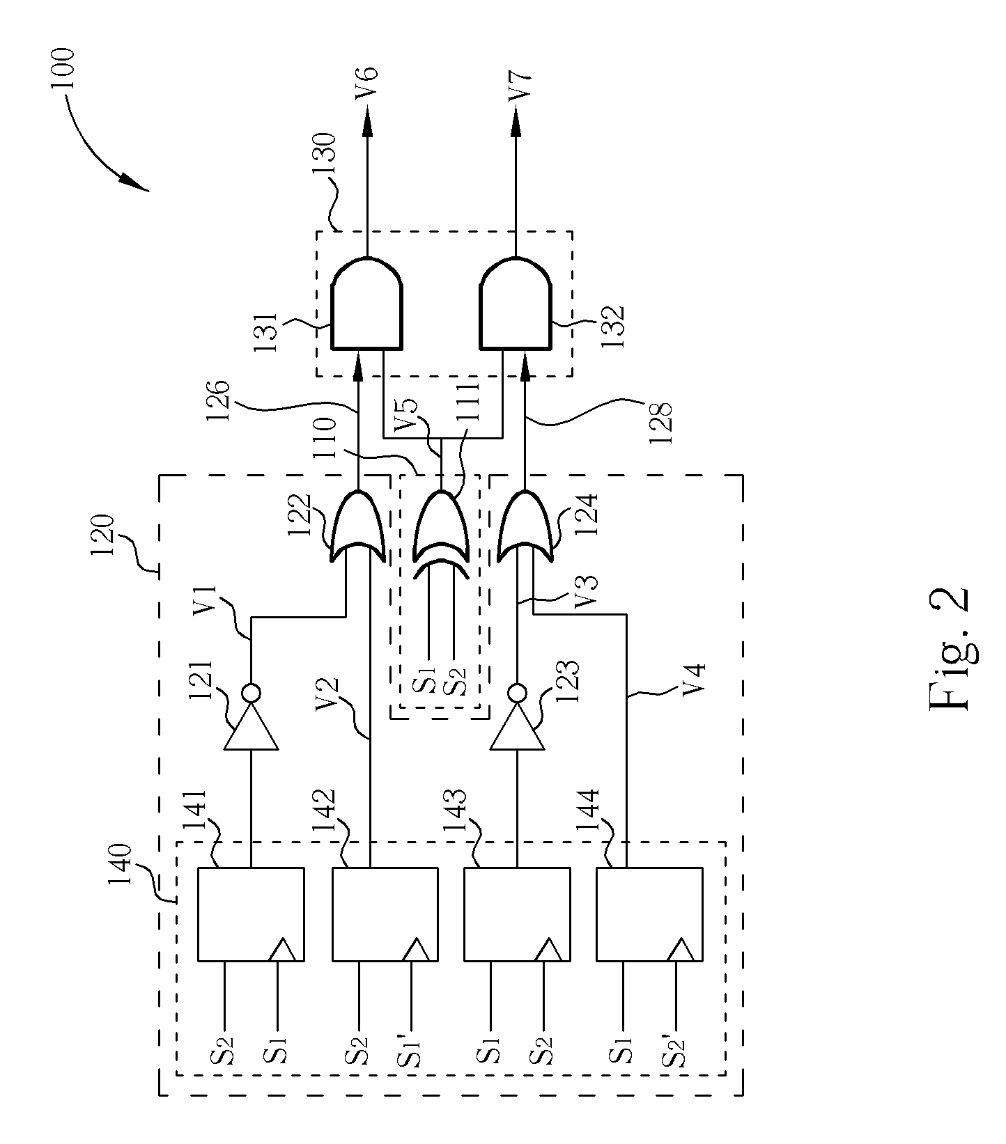
[0025] Please refer to FIG. 2 and FIG. 3. FIG. 2 is a diagram of the phase detector 100 of a first embodiment according to the present disclosure. FIG. 3 is a diagram of waveforms of signals shown in FIG. 2. As shown in FIG. 2, the phase detector 100 comprises a plurality of logic gates and flip-flops. The operation and function of the logic gates and the flip-flops will be illustrated in the following disclosure.

[0026] As shown in FIG. 2, the difference determining module 110 comprises an XOR logic gate 111, which receives the two signals S1 and S2. The XOR logic gate 111 performs an XOR operation upon the two signals S1 and S2. Therefore, in FIG. 3, the XOR logic gate 111 outputs a pulse if the two signals correspond to different logic levels (shown as the signal V5).

[0027] In one embodiment, the sampling module 140 comprises four D-type flip-flops 141, 142, 143, and 144, which respectively receive the two signals S1 and S2. Here, the D-type flip-flop 141 is illustrated first. Th...

second embodiment

[0033] Please refer to FIG. 4 and FIG. 5. FIG. 4 is a diagram of the phase detector 100 of a FIG. 5 is a diagram of waveforms of signals shown in FIG. 4. As shown in FIG. 4, the phase detector 100 comprises a plurality of logic gates and flip-flops.

[0034] Primarily, in FIG. 4, the operations and the functions of the devices having the same number as the devices shown in FIG. 2 also perform similar functions. In this embodiment, the only difference is that AND logic gates 422 and 424 are utilized to replace the OR logic gates 122 and 124 shown in FIG. 2. Therefore, an AND operation is performed upon the outputs of the NOT logic gate 121 and the D-type flip-flop 142. In other words, in this embodiment, when the signals V1 and V2 both correspond to 1, this means that the signal S1 leads the signal S2 such that the detection signal 126 outputted by the AND logic gate 422 corresponds to 1. Otherwise, the detection signal 126 corresponds to 0. On the other hand, when the signals V3 and V...

third embodiment

[0038] Surely, there is another way to determine the phase relationship. For example, in the case where the OR gates 122 and 124, and the AND gates 422 and 424 cannot be utilized, another method must exist. Please refer to FIG. 6, which is a diagram of the phase detector 100 of a In this embodiment, we can directly utilize the output of the D-type flip-flops 142 and 144 because they can react to the phase relationship. Similarly, the XOR gate 111 still determines the degree of the phase difference. Therefore, the voltage V6 and V7 respectively represents the leading / lagging phase difference.

[0039] Furthermore, we can utilize only half of the circuits. Please refer to FIG. 7, which is a diagram of a phase detector of a fourth embodiment. In this embodiment, only the D-type flip-flop 142 is used. Since one of the D-type flip-flop 142 or 144 is sufficient to determine the phase difference. That is, if the D-type flip-flop 142 outputs a high logic level 1, this means that the signal S1...


PUM


Abstract

A phase detector for detecting a phase difference between a first signal and a second signal is disclosed. The phase detector includes: a difference determining module, a phase leading/lagging determining module, and a phase determining module. The difference determining module is used for outputting a pulse having a period in which a logic level of the first signal is different from a logic level of the second signal. The phase leading/lagging determining module is used for outputting an detection signal to identify a phase leading/lagging relationship between the first signal and the second signal. The phase determining module is coupled to the difference determining module and the phase leading/lagging determining module for combining the pulse and the detection signal to output a result signal, wherein the result signal comprises difference and leading/lagging information between the first and the second signal.

Description

CROSS REFERENCE TO RELATED APPLICATIONS [0001] The application claims the benefit of U.S. Provisional Application No. 60 / 596,041, which was filed on Aug. 25, 2005.BACKGROUND [0002] The disclosure relates to phase differences between signals, and more particularly, to a phase detector and a related phase detecting method for detecting the phase differences between signals. [0003] A phase detector is an important device component in a signal processing system. A phase detector is used to determine the phase difference and the lead / lag relationship between two input signals. Phase detectors are widely used in many applications, such as communication, servo control, and phase lock loop. [0004] Conventionally, a phase detector can be implemented by introducing state machine. However, a glitch of an input signal may trigger a false state transition, leading to continuous errors of the result of phase detection. Therefore, detecting the phase difference between two signals without inducing...

Claims


Application Information

Patent Timeline
Patent Type & Authority Applications(United States)
IPC IPC(8): H03D3/24
CPCH03D13/004
Inventor HSU, TSE-HSIANGLIU, SHIUE-SHIN
Owner MEDIATEK INC
Why Eureka
Try Eureka