Vacuum evacuation device and method, and substrate processing apparatus and method

a technology of vacuum evacuation device and substrate, which is applied in the direction of non-positive displacement fluid engines, axial flow pumps, non-positive displacement pumps, etc., can solve the problems of loss of synchronization, increase in motor power consumption, and delay in deceleration

Inactive Publication Date: 2007-03-01
EBARA CORP
View PDF3 Cites 34 Cited by
  • Summary
  • Abstract
  • Description
  • Claims
  • Application Information

AI Technical Summary

Benefits of technology

[0016] With this construction, a specified rotational speed for the vacuum pump is calculated based on process information related to process reaction, and the vacuum pump can be brought to the specified speed suitable for the process reaction before the first control. Therefore, it is possible to bring the process chamber to a pressure condition suitable for the process reaction in a short period without the vacuum pump being overloaded in the first control, regardless of the process reaction condition.
[0020] With this construction, a specified rotational speed for one of the first vacuum pump and the second vacuum pump is calculated based on process information related to process reaction, and the one vacuum pump can be brought to the specified speed suitable for the process reaction before the first control. Therefore, it is possible to bring the process chamber to a pressure condition suitable for the process reaction in a short period without the vacuum pump being overloaded in the first control, regardless of the process reaction condition.
[0022] With this construction, a specified rotational speed for at least one of the first vacuum pump and the second vacuum pump is calculated based on process information related to process reaction, and the at least one vacuum pump can be brought to the specified speed suitable for the process reaction before the first control. Therefore, it is possible to bring the process chamber to a pressure condition suitable for the process reaction in a short period without the vacuum pump being overloaded in the first control, regardless of the process reaction condition. The control means may calculate respective specified rotational speeds for the first vacuum pump and the second vacuum pump based on process information related to the process reaction, and may perform a second control that brings the first vacuum pump and the second vacuum pump to the respective specified rotational speeds before the first control. In this way, it is possible to appropriately perform control over a wider pressure range and control involving pressure changes with a high pressure change rate.
[0024] With this construction, it is possible to bring the process chamber to a pressure condition suitable for process reaction in a short period without the vacuum pump being overloaded in the first control, regardless of the process reaction condition. It is thus possible to reduce the time required to process the substrate.
[0032] With this construction, a specified rotational speed for the vacuum pump is calculated based on process information, and the vacuum pump can be brought to the specified speed before the first control. Therefore, it is possible to bring the process chamber to a desired pressure condition in a short period without the vacuum pumps being overloaded in the first control.
[0036] As described above, according to the present invention, the control means calculates a specified rotational speed for the vacuum pump based on process information related to process reaction, and the vacuum pump can be brought to the specified speed suitable for the process reaction before the first control. Therefore, it is possible to bring the process chamber to a pressure condition suitable for the process reaction in a short period without the vacuum pump being overloaded in the first control, regardless of the process reaction condition.

Problems solved by technology

However, in case of using a turbo molecular pump including a magnetic bearing which operates in a vacuum in a non-contacting manner, for example, deceleration takes time due to the absence of friction which acts on the rotor.
Further, in the case where a process condition exceeding the evacuation capacity of the turbo molecular pump is given while cleaning the process chamber or the like, increase in the motor power consumption and a loss of synchronization may be caused due to overload operation.
Rotor runout may also be caused, which could result in the rotor contacting with the protective bearing.

Method used


Image

  • Vacuum evacuation device and method, and substrate processing apparatus and method
  • Vacuum evacuation device and method, and substrate processing apparatus and method
  • Vacuum evacuation device and method, and substrate processing apparatus and method

Examples


first embodiment

[0064] the present invention will be hereinafter described with reference to the drawings. The same or corresponding parts are denoted in all the drawings with the same reference numerals, and redundant description is not repeated.

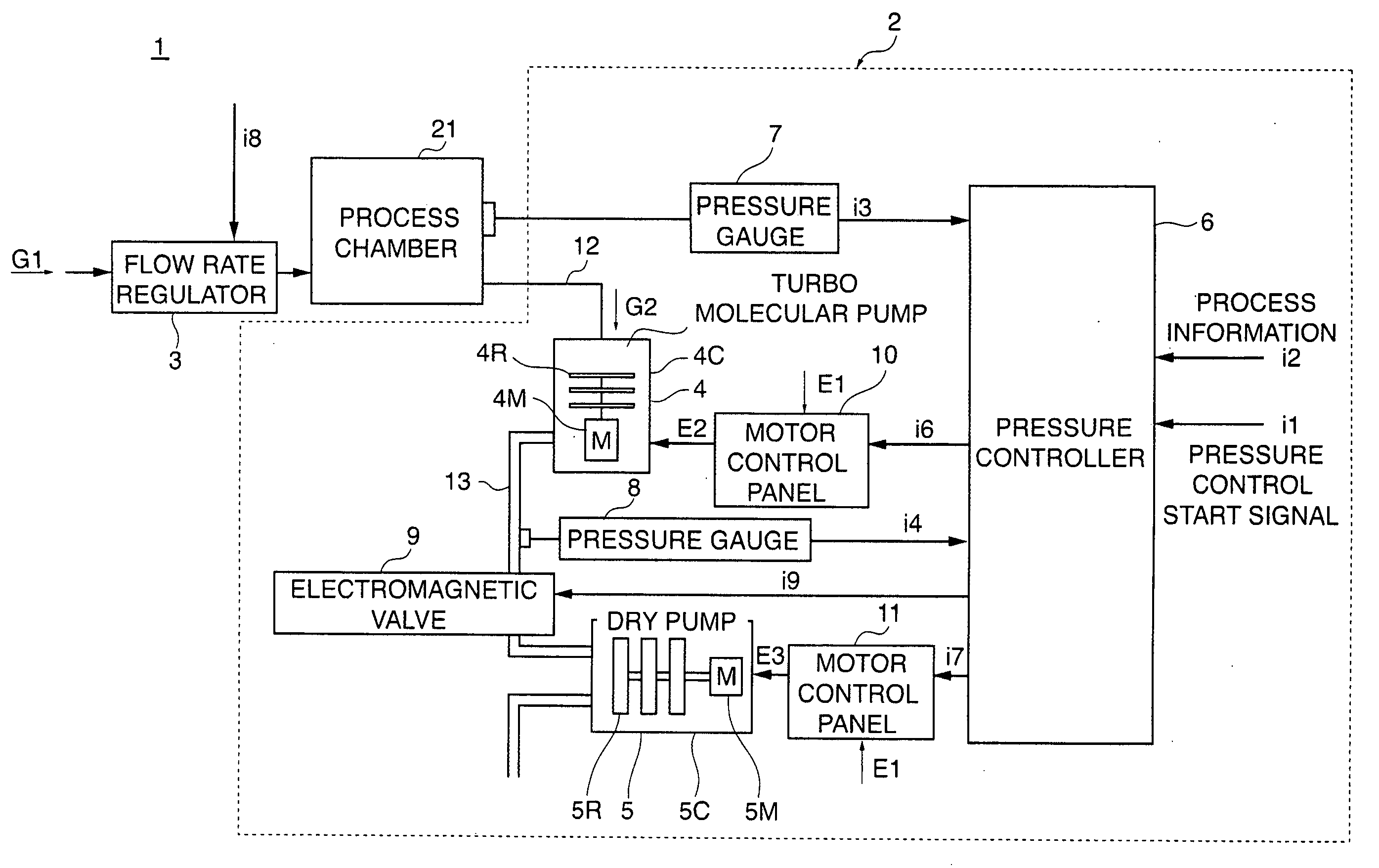
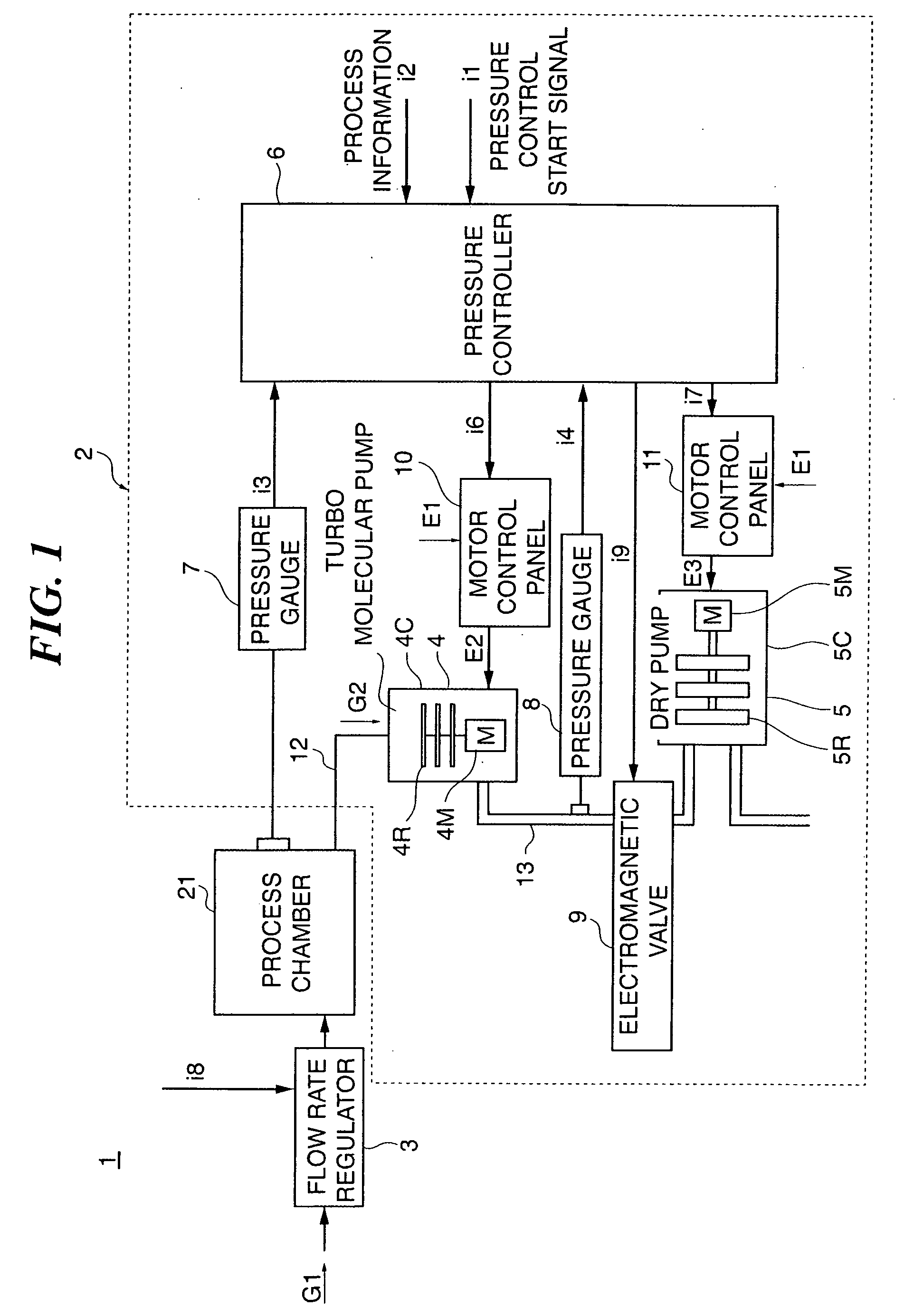
[0065] As shown in FIG. 1, a substrate processing apparatus 1 according to the first embodiment of the present invention includes a vacuum evacuation device 2 (the part surrounded by the broken line in the drawing), an airtight process chamber 21 in which a process reaction is caused, and a flow rate regulator 3 for regulating the flow rate of a process gas G1 to be introduced into the process chamber 21. The process gas G1 may be, for example, a nitrogen gas, a helium gas, an argon gas, an inert gas as a mixture of these gases, a cleaning gas such as a ClF3 gas, and a reaction gas such as a SiH2Cl2 gas.

[0066] The vacuum evacuation device 2 includes a turbo molecular pump 4, as a first vacuum pump, connected to the process chamber 21 via exhaust piping 12...

second embodiment

[0168] the present invention will be hereinafter described with reference to the drawings. The same or corresponding parts are denoted in all the drawings with the same reference numerals, and redundant description is not repeated.

[0169] As shown in FIG. 12, a substrate processing apparatus 1 according to the second embodiment of the present invention includes a vacuum evacuation device 2 (the part surrounded by the broken line in the drawing), an airtight process chamber 21 in which a process reaction is caused, and a flow rate regulator 3 for regulating the flow rate of a process gas G1 to be introduced into the process chamber 21. The process gas G1 may be, for example, a nitrogen gas, a helium gas, an argon gas, an inert gas as a mixture of these gases, a cleaning gas such as a ClF3 gas, and a reaction gas such as a SiH2Cl2 gas.

[0170] The vacuum evacuation device 2 includes a booster dry pump 24 (rotational speed N24) (booster pump 24 hereafter), as a first vacuum pump, connect...


PUM


Abstract

A vacuum evacuation device 2 of the invention comprises a vacuum pump 4,5 for exhausting a gas G2 in a process chamber 21 into which a process gas G1 is introduced and in which a process reaction is performed, to form a vacuum in said process chamber 21; and a control means 6 for performing a first control that regulates the rotational speed of said vacuum pump 4,5 such that a pressure condition in said process chamber 21 reaches a pressure condition suitable for said process reaction during said process reaction, wherein said control means 6 calculates a specified rotational speed for said vacuum pump 4,5 based on process information related to said process reaction, and performs a second control that brings said vacuum pump 4,5 to said specified rotational speed before said first control. The vacuum evacuation device 2 is capable of bringing the pressure in a process chamber 21 to the target pressure in a short period without a vacuum pump 4,5 being overloaded, regardless of the process reaction condition.

Description

BACKGROUND OF THE INVENTION [0001] 1. Technical Field [0002] The present invention relates to a vacuum evacuation device and method for regulating the rotational speed of a vacuum pump for exhausting a gas from a process chamber to control the pressure condition in the process chamber, and a substrate processing apparatus for evacuating a process chamber using the vacuum evacuation device to process a substrate in the process chamber and a substrate processing method for evacuating a Process chamber using the vacuum evacuation method to process a substrate in the process chamber. [0003] 2. Related Art [0004] As shown in FIG. 21, a conventional vacuum evacuation device 102 includes a turbo molecular pump 104 for exhausting a gas G2 from a process chamber 121 into which a process gas G1 is introduced at a flow rate regulated by a flow rate regulator 103, a dry pump 105 for exhausting the gas G2 from the exhaust side of the turbo molecular pump 104, and a pressure controller 106 for re...

Claims


Application Information

Patent Timeline
Patent Type & Authority Applications(United States)
IPC IPC(8): F04B49/06
CPCF04D27/0261F04D19/042Y02B30/70
Inventor ISHII, KATSUTOSHINAKAO, KENASANO, TAKANOBUUMEZAWA, KOTAOGAMINO, HIROAKIURATA, TADASHIUSUI, KATSUAKIINOUE, MASAFUMISEKIGUCHI, SHINICHIYAMASAKI, HIRONOBU
Owner EBARA CORP
Why Eureka
Try Eureka