System and method for controlling hydrogen elimination during carbon nanotube synthesis from hydrocarbons

a carbon nanotube and carbon nanotube technology, applied in the direction of carbonsing rags, physical/chemical process catalysts, coatings, etc., can solve the problems of reducing fuel input and difficult process use in manufacturing operations

Inactive Publication Date: 2007-03-01
UT BATTELLE LLC
View PDF3 Cites 7 Cited by
  • Summary
  • Abstract
  • Description
  • Claims
  • Application Information

AI Technical Summary

Problems solved by technology

However, reducing the fuel input renders the process difficult to use in manufacturing operations.

Method used


Image

  • System and method for controlling hydrogen elimination during carbon nanotube synthesis from hydrocarbons
  • System and method for controlling hydrogen elimination during carbon nanotube synthesis from hydrocarbons
  • System and method for controlling hydrogen elimination during carbon nanotube synthesis from hydrocarbons

Examples


Embodiment Construction

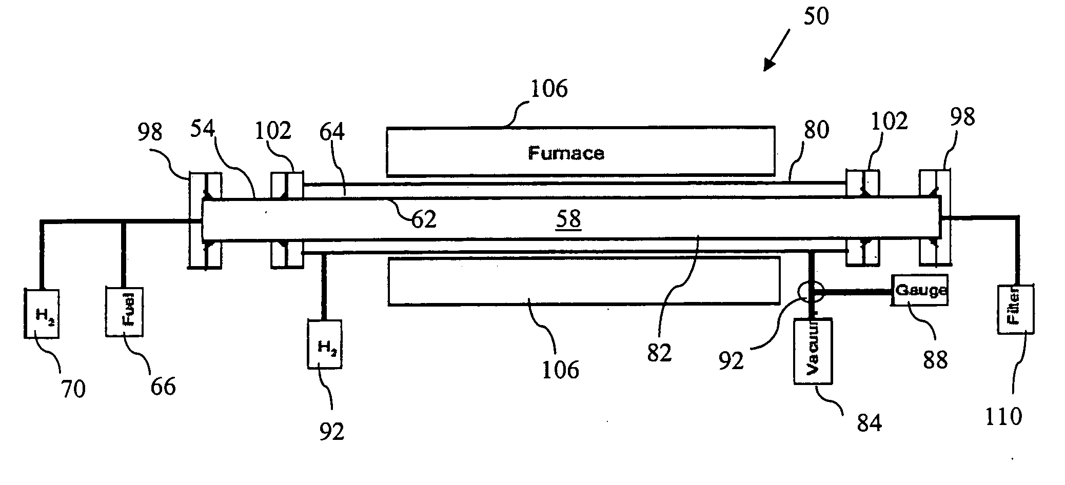
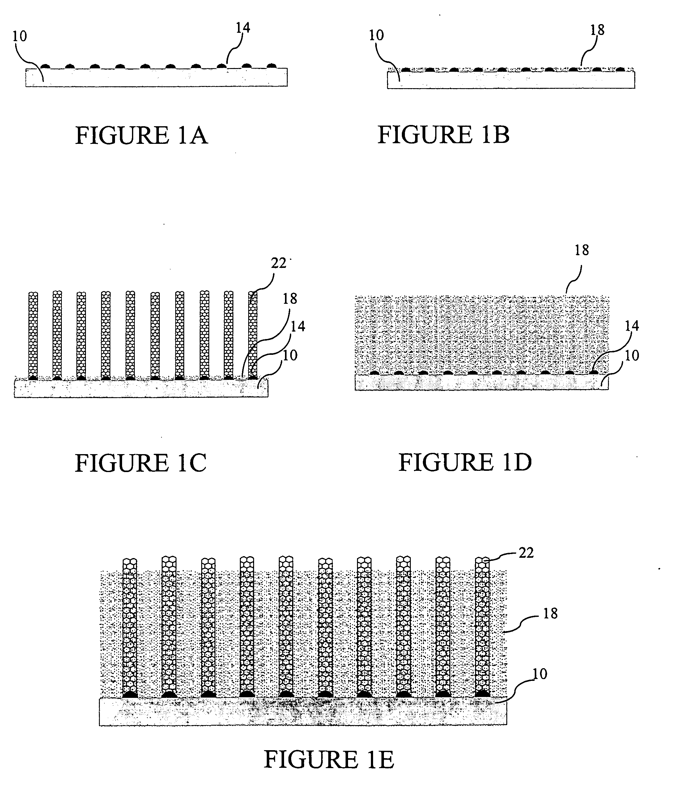
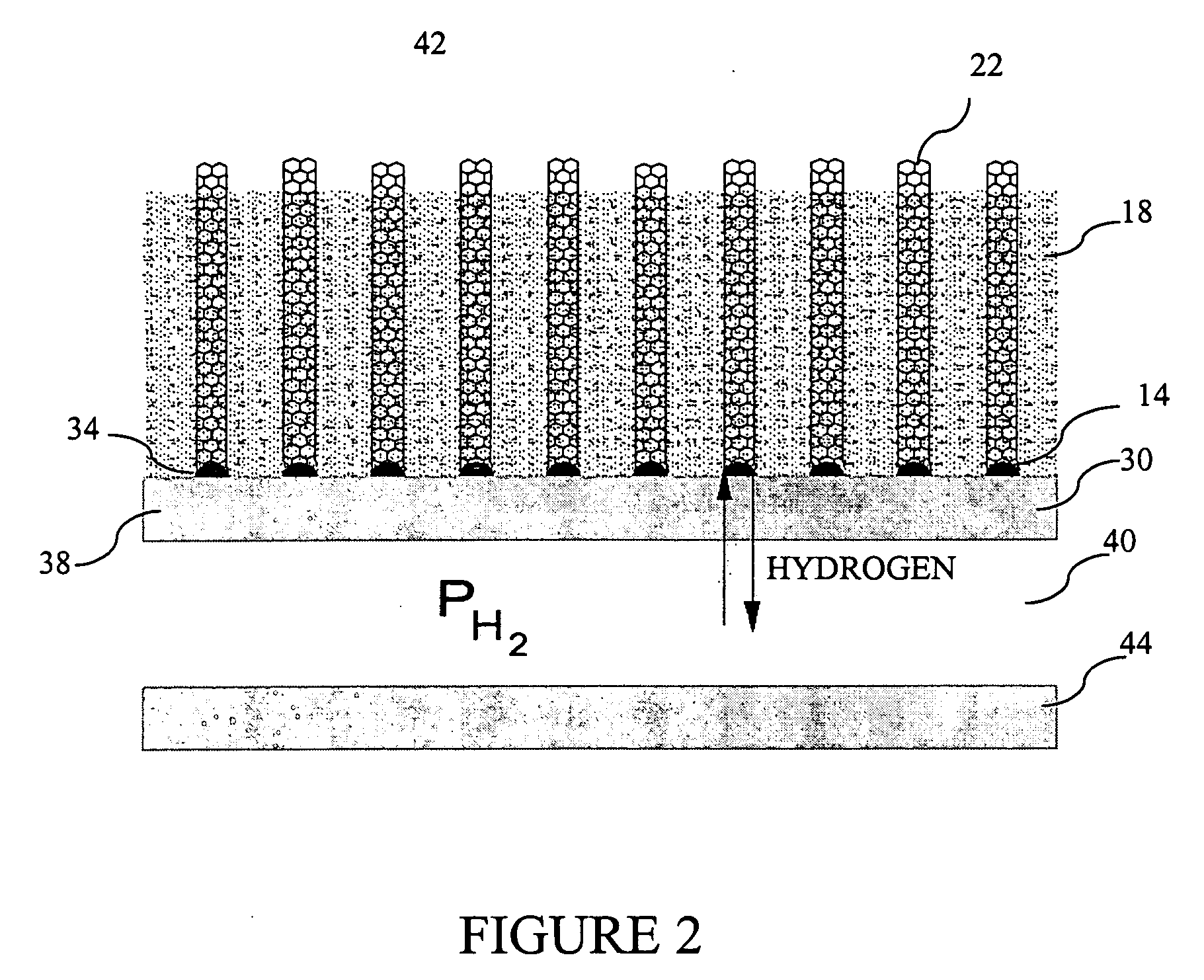
[0017] The chemical vapor deposition (CVD) synthesis of carbon nanotubes (CNT) from hydrocarbon in one method according to the invention utilizes a catalyst that is provided on a catalyst support. There is shown in FIG. 1A a catalyst support 10 having thereon a plurality of catalyst particles 14. The carbon nanotubes are grown on surfaces of the catalyst 14 by reactive dehydrogenation of a high-temperature-stable hydrocarbon intermediate known as precursor soot. Dehydrogenation must occur at the interface between the catalyst 14 and the nanotube and the precursor soot material in order for the tube to grow. Precursor soot is an intermediate to the formation of soot. It forms during the pyrolysis of any hydrocarbon. It is a high-temperature-stable form of liquid hydrocarbon which has a substructure that is continuously rearranging itself due to rapid exchange of hydrogen between the subunits from large amounts of carbon free radicals. Precursor soot is extremely reactive due to the p...


PUM

PropertyMeasurementUnit
partial pressureaaaaaaaaaa
pressureaaaaaaaaaa
proton conductiveaaaaaaaaaa

Abstract

A system and method for producing carbon nanotubes by chemical vapor deposition includes a catalyst support having first and second surfaces. The catalyst support is capable of hydrogen transport from the first to the second surface. A catalyst is provided on the first surface of the catalyst support. The catalyst is selected to catalyze the chemical vapor deposition formation of carbon nanotubes. A fuel source is provided for supplying fuel to the catalyst.

Description

STATEMENT REGARDING FEDERALLY SPONSORED RESEARCH OR DEVELOPMENT [0001] The United States Government has rights in this invention pursuant to Contract No. DE-AC05-000R22725 between the United States Department of Energy and UT-Battelle, LLC.CROSS-REFERENCE TO RELATED APPLICATIONS [0002] Not applicable. BACKGROUND OF THE INVENTION [0003] Hydrocarbon synthesized carbon nanotubes are grown on catalyst surfaces by reactive dehydrogenation of a high-temperature-stable hydrocarbon intermediate known as precursor soot. Dehydrogenation must occur at the interface between the metal with the nanotube and the precursor soot material in order for the nanotube to grow. The precursor soot can only lose hydrogen at the interface with the surrounding medium. Consequently, as the precursor soot film grows thicker hydrogen must diffuse further though the precursor soot medium in order to escape into the gas phase. It is this thickening of the precursor soot layer that causes the deactivation of the ca...

Claims


Application Information

Patent Timeline
Patent Type & Authority Applications(United States)
IPC IPC(8): D01F9/12B01J8/02
CPCB82Y30/00B82Y40/00D01F9/32D01F9/127C01B31/0233C01B32/162Y10S977/843
Inventor REILLY, PETER T.A.
Owner UT BATTELLE LLC
Why Eureka
Try Eureka