Prosthetic leg having electronically controlled prosthetic knee with regenerative braking feature

a prosthetic knee and electronic control technology, applied in the field of prosthetic legs with electronic control prosthetic knees, can solve the problems of generating electrical power, essentially waste of mechanical energy output of amputees, etc., and achieve the effect of reducing the necessary energy expenditure of patients, absorbing more energy, and enhancing other portions of the gait cycl

Inactive Publication Date: 2007-03-01
WILLOWWOOD GLOBAL LLC
View PDF45 Cites 161 Cited by
  • Summary
  • Abstract
  • Description
  • Claims
  • Application Information

AI Technical Summary

Benefits of technology

[0014] During normal gait, the human knee has been shown to absorb more energy than it expends. This is true for both a natural and prosthetic knee joint. Consequently, a properly designed prosthetic knee could actually operate in a manner that results in a net generation of electrical power.
[0015] Therefore, it is possible to collect the energy that is available from the knee during terminal impact and heel rise, and to then use this energy to augment other portions of the gait cycle or to power some other device. It has been determined that much of the excess energy that can be potentially recovered by a prosthetic knee originates at a patient's hip. For this reason, one such example would be to absorb energy from the knee and transfer this energy to hip extension, thereby returning the energy to it's original source, and reducing the necessary energy expenditure of the patient.

Problems solved by technology

Yet, as discussed above, the use of the vast majority of known AK prosthetic legs results in substantial amounts of mechanical energy output by the amputee being essentially wasted.
Consequently, a properly designed prosthetic knee could actually operate in a manner that results in a net generation of electrical power.

Method used


Image

  • Prosthetic leg having electronically controlled prosthetic knee with regenerative braking feature
  • Prosthetic leg having electronically controlled prosthetic knee with regenerative braking feature
  • Prosthetic leg having electronically controlled prosthetic knee with regenerative braking feature

Examples


Embodiment Construction

)

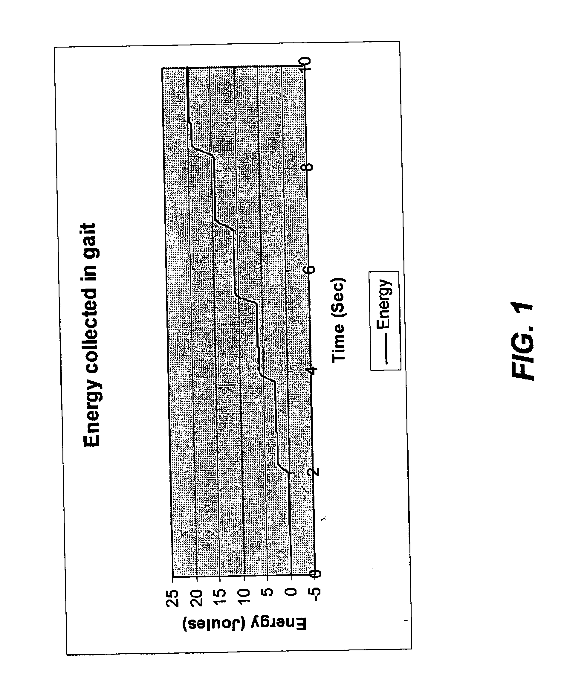
[0049] As discussed above, it has been determined that for a large percentage of an individual's gait cycle, and particularly when descending stairs or slopes, the knee joint actually absorbs more energy than it must deliver. This is true for both a natural knee and for a prosthetic knee for use by an amputee. The absorbed energy results from the knee's required and repeated resistance to bending in the extension or flexion directions. This absorbed energy is typically dissipated as heat by known passive prosthetic knees. However, it is also possible to convert this absorbed mechanical energy into electrical energy, and to store the electrical energy for later use.

[0050] As can be observed by reference to the graph of FIG. 1, when using an AK prosthesis, energy must be absorbed from the knee during an amputee's gait cycle. The data shown in FIG. 1 was collected from an electronically regulated knee that was designed to simply mimic the function of current prosthetic knee designs. ...


PUM


Abstract

A prosthetic leg having an electronically controlled regenerative prosthetic knee. In certain embodiments of the present invention the knee may be passive, whereby it is used only to generate electrical energy. In other embodiments, the knee may be active, whereby it can be used to assist with or completely control gait, as well as to generate electrical energy. The knee makes use of an actuator motor/generator to control gait and/or to generate electrical energy. An electronic control system is provided to control overall operation of the prosthetic leg, to distribute generated electrical energy, and to transfer excess electrical energy to one or more storage devices for later use. A prosthetic leg of the present invention having an active prosthetic knee may be especially helpful in assisting an amputee with activities that impart a high torque load to the knee joint.

Description

BACKGROUND AND SUMMARY OF THE INVENTION [0001] The present invention relates to a prosthetic limb having a regenerative and electronically controlled prosthetic joint. More specifically, the present invention is directed to a prosthetic leg having a regenerative and electronically controlled knee joint capable of converting mechanical energy, normally dissipated during the gait cycle, into electrical energy. The electrical energy may either be used as generated, or may be stored for later use. Stored electrical energy can be subsequently released as necessary to assist with an amputee's gait cycle or to provide power to various other electrical energy consuming devices associated with the amputee. [0002] Lower limb amputations can be classified as one of two types: below knee (BK), or above knee (AK). A below knee amputation occurs along a line through the tibia and fibula of the lower leg; with the knee joint remaining intact. An above knee amputation, however, is a transfemoral am...

Claims


Application Information

Patent Timeline
Patent Type & Authority Applications(United States)
IPC IPC(8): A61F2/70A61F2/64
CPCA61F2/60A61F2220/0025A61F2/68A61F2/72A61F2002/30527A61F2002/701A61F2002/704A61F2002/705A61F2002/745A61F2002/747A61F2002/7625A61F2002/7635A61F2002/764A61F2002/7645A61F2/64A61F2/70A61F2002/30523A61F2/74
Inventor HAYNES, MICHAEL L.TAYLOR, MARC D.
Owner WILLOWWOOD GLOBAL LLC
Why Eureka
Try Eureka