Work transfer device for press machines

Active Publication Date: 2007-03-08
KOMATSU LTD
View PDF5 Cites 13 Cited by
  • Summary
  • Abstract
  • Description
  • Claims
  • Application Information

AI Technical Summary

Benefits of technology

[0035] According to the first aspect of the present invention, the feed carrier is driven by the feed drive mechanism so as to move relative to the pair of the bars in the work transfer direction. Further, the base is driven by the lift drive mechanism so as to move relative to the feed carrier in the lift direction. Thus the work transfer device can perform at least two-dimensional motion in the work transfer direction and the lift direction.
[0036] Since the feed carrier moves relative to the bars in the work transfer direction, the moving range of feed carrier the in the work transfer direction becomes wide. Also, since the moving distance in the lift direction is usually smaller than the moving distance in the work transfer direction, the length of the feed carrier in the lift direction becomes small. Thus the feed carrier can be made small and light, and the feed drive mechanism and lift drive mechanism with small capacity can be used, therefore it becomes possible to install the feed drive mechanism and lift drive mechanism on the moving bolster.
[0037] Accordingly, different from the conventional art, since the feed box having a feed drive section housed therein becomes unnecessary, there is no feed box projected from the press main body, so that the press device as a whole can be downsized. Further, since no feed box is projected, a work carrying-out robot or the like

Problems solved by technology

However, in the case of the movements in the feed direction, the clamp direction, and the lift direction are driven by the respective cams, to obtain a variable motion pattern of the feed bar 114, plu

Method used


Image

  • Work transfer device for press machines
  • Work transfer device for press machines
  • Work transfer device for press machines

Examples


Example

First Embodiment

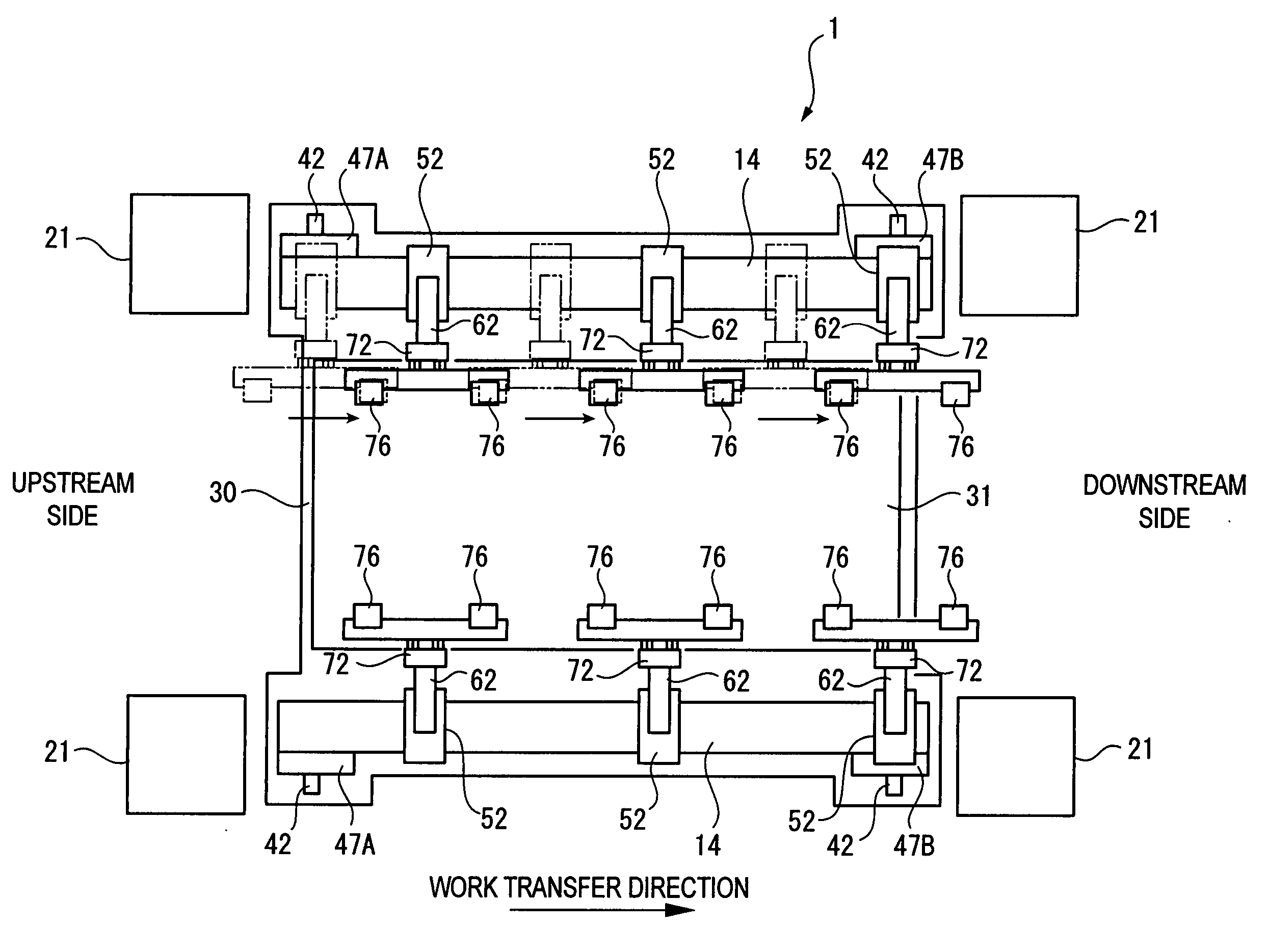
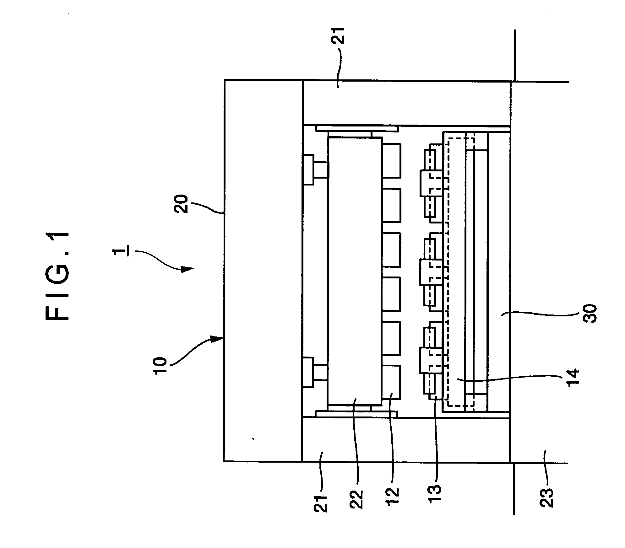
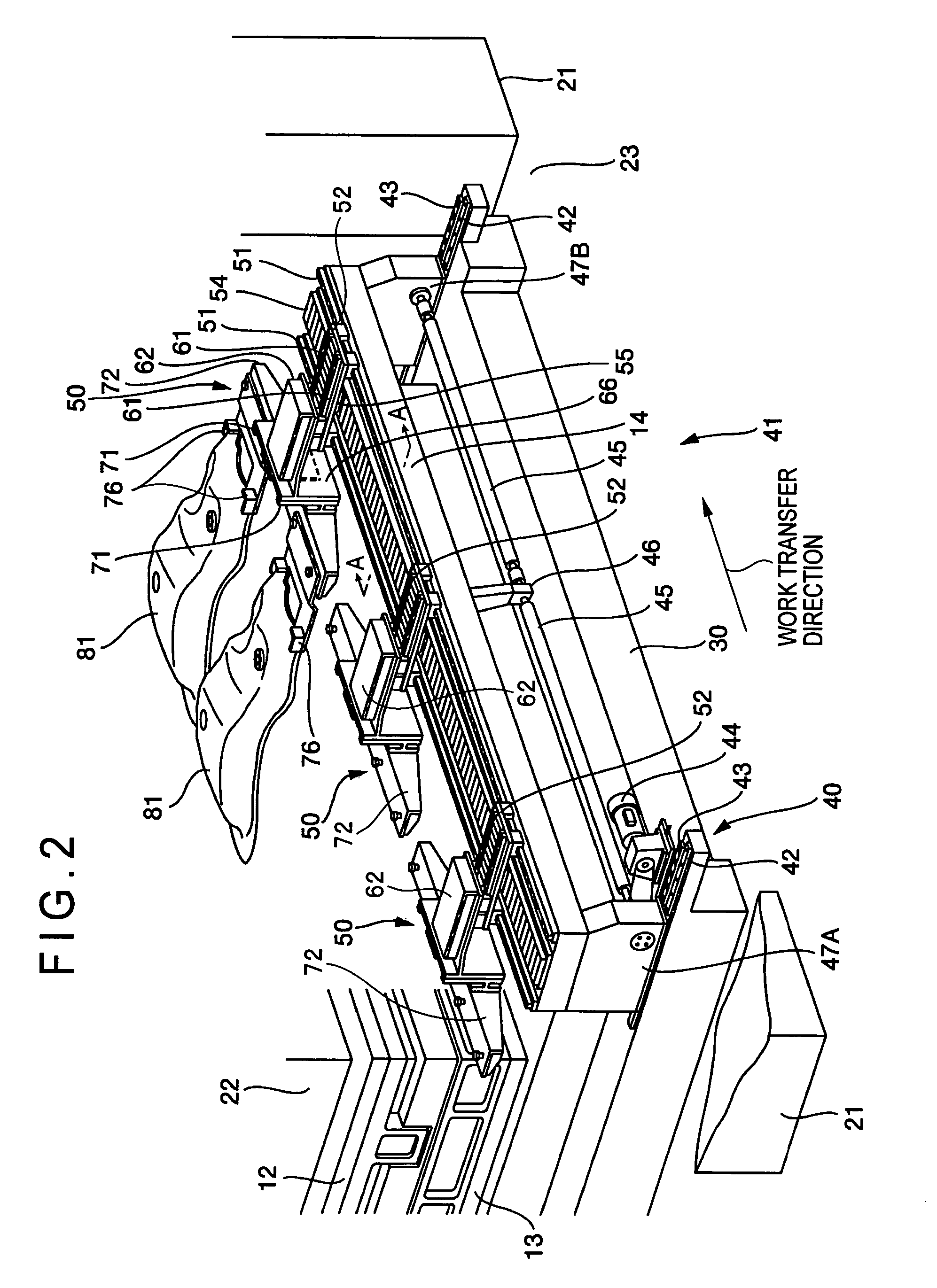
[0071]FIG. 1 is a front elevational view showing a transfer press (press machine) 1 equipped with a work transfer device in a first embodiment of the present invention. FIG. 2 is a perspective view showing a transfer feeder 41 which is the work transfer device. FIGS. 3 to 5 are partly enlarged views of the transfer feeder 41.

[0072] As shown in FIG. 1, four columnar uprights 21 are erected on a bed 23 disposed in the lower portion of a press frame 10 of the transfer press 1, and a crown 20 is provided above the uprights 21. A slide drive device is built into the crown 20 for driving a slide 22 disposed below the crown 20 upward and downward. Upper dies 12 are attached to a lower surface of the slide 22. Lower dies 13 are attached to an upper surface of a moving bolster 30 opposed to the slide 22, so that a work is press-formed by cooperation of the upper dies 12 with the lower dies 13. Above the moving bolster 30, a pair of bars 14, 14 are provided on the right and ...

Example

Second Embodiment

[0099] Next, a transfer feeder 41 A of a second embodiment will be described below with reference to FIG. 12. FIG. 12 is a perspective view showing a transfer feeder 41A which is the work transfer device. Like components are denoted by like numerals as of the first embodiment and the explanation thereof will be omitted.

[0100] Lower dies 13 (refer to FIG. 2) are attached to an upper surface of a moving bolster 30A opposed to the slide 22, so that a work is press-formed by cooperation of upper dies 12 (refer to FIG. 2) with the lower dies 13. A pair of bars 14A, 14A are provided on the right and left with the upper dies 12 and the lower dies 13 sandwiched therebetween, the pair of bars 14A, 14A extending in parallel in the work transfer direction.

[0101] To make the description easy to understand, only one of the pair of the bars 14A, 14A is showed in FIG. 12. As shown in FIG. 12, the front side (seen from FIG. 12) of the automatically movable moving bolster 30A is ...

Example

Third Embodiment

[0113] Next, a transfer feeder 41B of a third embodiment will be described below with reference to FIG. 13. FIG. 13 is a perspective view showing the transfer feeder 41B which is the work transfer device. Like components are denoted by like numerals as of the first embodiment and the explanation thereof will be omitted.

[0114] The third embodiment differs from the first embodiment in that the feed carriers 52 adjacent to each other are connected to each other via a connector 56. Accordingly, the plurality of feed carriers 52 are so arranged that the feed carriers 52 adjacent to each other are connected to each other with a predetermined interval. Since all of feed carriers 52 supported by the single bar 14 are operated in an interlocked manner, it is unnecessary to provide a feed drive mechanism for each of the feed carriers 52. FIG. 13 shows a case where only the feed carrier 52 on the upstream side is provided with a linear motor (feed drive mechanism) 53B.

[0115]...


PUM


Abstract

A transfer feeder 41 for a transfer press 1 comprises a pair of bars 14 provided on a moving bolster 30 in parallel with a work transfer direction, a feed carrier 52 held by the bars 14 and movable in the work transfer direction, a clamp carrier 62 held by the feed carrier 52 and movable in the direction of clamp, and a lift carrier 72 supported by the clamp carrier 62 and movable in the direction of lift. Since a large drive mechanism is unnecessary, simplification of the construction can be enhanced. Further, since the whole of a transfer feeder 41 is provided on a moving bolster 30, the moving bolster 30 in its entirety can be carried out of the transfer press 1, thus facilitating die exchanging operation.

Description

TECHNICAL FIELD [0001] The present invention relates to a work transfer device for press machines. BACKGROUND ART [0002]FIG. 17 shows a transfer press 100 as a conventional press machine. As shown in FIG. 17, four uprights 121 are erected on a bed 123 located in a lower portion of a press frame 110 of the transfer press 100, and a crown 120 is provided above the uprights 121. A slide drive device is built into the crown 120 for driving a slide 122 disposed below the crown 120 so that the slide 122 moves upward and downward. Upper dies 112 are attached to a lower surface of the slide 122. Lower dies 113 are attached to an upper surface of a moving bolster 130 opposed to the slide 122, so that a work is press-formed by cooperation of the upper dies 112 with the lower dies 113. A pair of bars 114, 114 are provided on the right and left with the upper dies 112 and the lower dies 113 sandwiched therebetween, the pair of bars 114, 114 extending in parallel. The feed bars 114, 114 are prov...

Claims


Application Information

Patent Timeline
IPC IPC(8): B21J11/00B21D43/05B21D43/10
CPCB21D43/10B21D43/05
Inventor SHIROZA, KAZUHIKO
Owner KOMATSU LTD
Why Eureka
Try Eureka