
Scanning microscope and method for examining a sample by using scanning microscopy

a scanning microscope and sample technology, applied in the field of scanning microscopes, can solve the problems of inability to compensate or calculate in the context of image processing, large light loss, and laser scanning microscopes

Active Publication Date: 2007-03-08
LEICA MICROSYSTEMS CMS GMBH
View PDF11 Cites 25 Cited by
  • Summary
  • Abstract
  • Description
  • Claims
  • Application Information

AI Technical Summary

Benefits of technology

[0013] A further object of the present invention is to describe a method that enables both manipulation of a sample in at least one region and (preferably simultaneous) observation of the sample, with the intention of largely avoiding the disadvantages (namely image artifacts and light output loss) known from the existing art.
[0043] Condenser-side incoupling of the manipulation light has the advantage that the scanning image field is not restricted. An alignment capability should exist, however, so that the focal planes of the illumination light beam and of the manipulation illumination pattern can be brought into congruence or, if desired, allowed to overlap slightly.

Problems solved by technology

The laser scanning microscope has the disadvantage that the light beams, namely the manipulation light beam and the scanning illumination light beam, coming from the beam deflection devices must be combined into one shared beam path, using a beam combiner, before entry into the objective.
A very particular disadvantage of the necessary beam combiner is that the interference bands produced thereby in the image change during the scanning procedure because of the changes in the angle of incidence of the moving beam, and thus cannot be compensated for or calculated out in the context of image processing.
The beam combiner furthermore produces a beam offset and thus results in considerable light losses.

Method used


Image

  • Scanning microscope and method for examining a sample by using scanning microscopy
  • Scanning microscope and method for examining a sample by using scanning microscopy
  • Scanning microscope and method for examining a sample by using scanning microscopy

Examples


Embodiment Construction

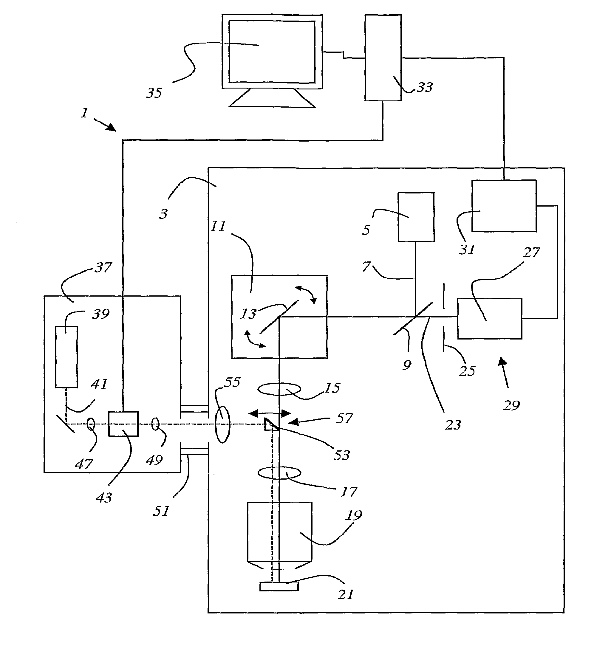
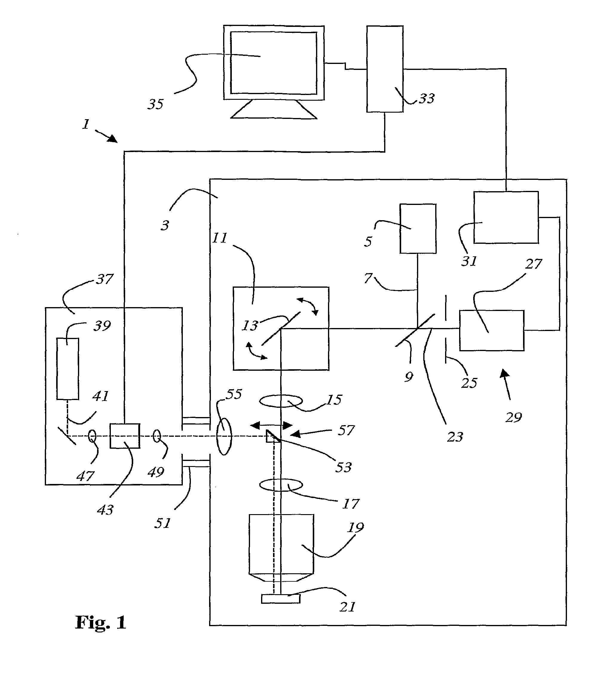
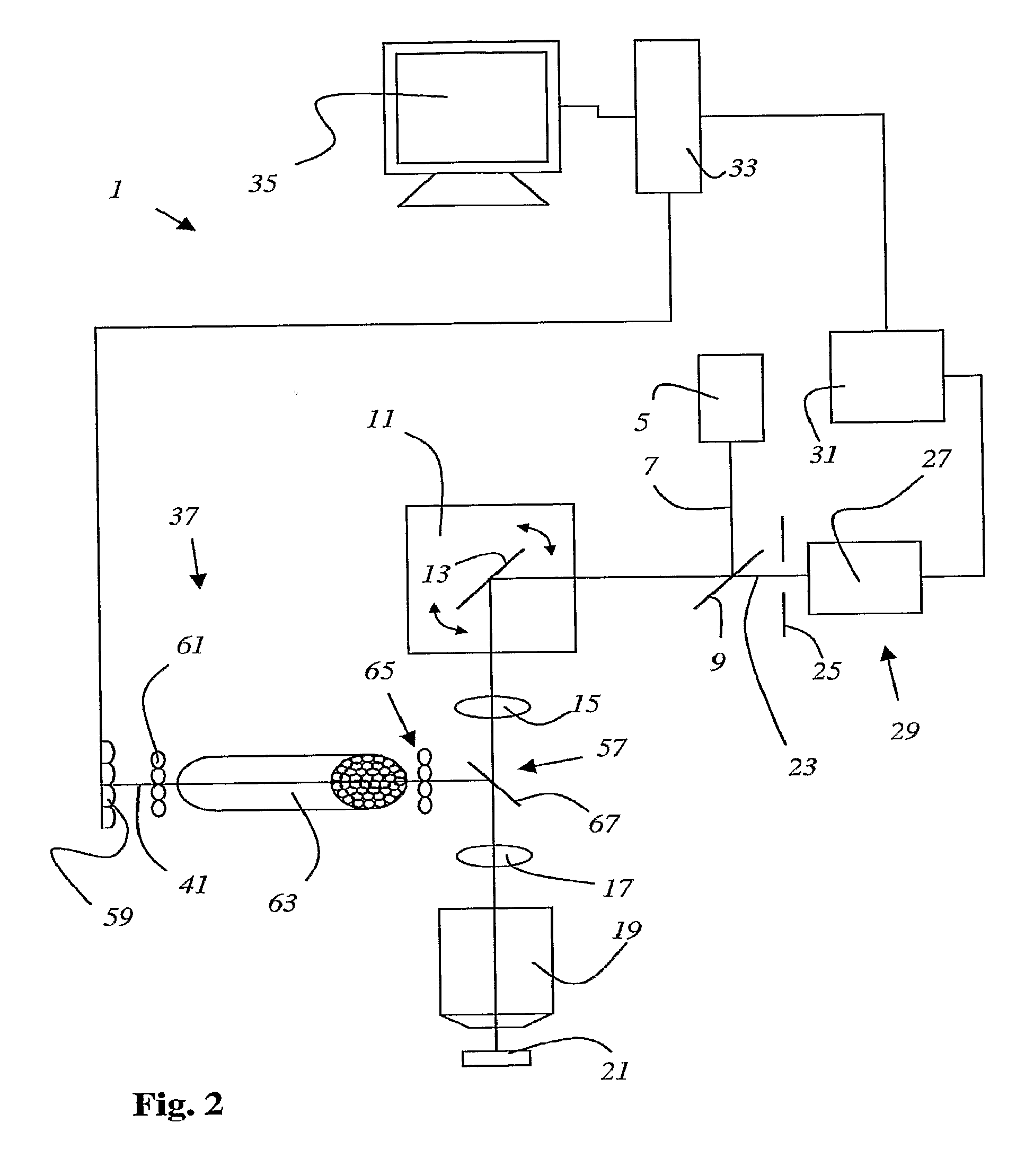
[0050]FIG. 1 shows a scanning microscope 1 according to the present invention that contains an imaging module 3 and a modularly attached means 37 for generating a manipulation illumination pattern. Imaging module 3 contains a light source 5 that emits an illumination light beam 7. Illumination light beam 7 is reflected by main beam splitter 9 to a beam deflection device 11 that contains a gimbal-mounted scanning mirror 13. Beam deflection device 11 guides illumination light beam 7 through scanning optical system 15, tube optical system 17, and microscope objective 19 and over or through sample 21. Detected light 23 emanating from sample 21 travels along the same light path, i.e. through microscope objective 19, tube optical system 17, scanning optical system 15, and via beam deflection device 11 back to main beam splitter 9, traverses the latter and detection pinhole 25 that follows it, and lastly arrives at a detector 29 that is configured as a photomultiplier 27. Detector 29 gener...


PUM


Abstract

A scanning microscope (1), having a light source (5) for generating an illumination light beam (7), having at least one objective (19) that focuses the illumination light beam onto and / or into a sample (21), having a beam deflection apparatus (11) that guides the focus of the illumination light beam over and / or through the sample, and having a detection device (29) that receives detected light emanating from the sample, is disclosed. The scanning microscope is characterized in that a means for generating a manipulation illumination pattern (37) is provided; and that imaging means image the manipulation illumination pattern onto and / or into the sample.

Description

RELATED APPLICATIONS [0001] This application is a Continuation of PCT application serial number PCT / EP2005 / 0501 10 filed on Jan. 12, 2005, which in turn claims priority to German application serial number 10 2004 016 253.0 filed on Apr. 2, 2004, both of which are incorporated herein by reference in their entirety.FIELD OF THE INVENTION [0002] The invention relates to a method for examining a sample using scanning microscopy. [0003] The invention furthermore relates to a scanning microscope, having a light source for generating an illumination light beam, having at least one objective that focuses the illumination light beam onto and / or into a sample, having a beam deflection apparatus that guides the focus of the illumination light beam over and / or through the sample, and having a detection device that receives detected light emanating from the sample. BACKGROUND OF THE INVENTION [0004] In scanning microscopy, a specimen is illuminated with a light beam in order to observe the refle...

Claims


Application Information

Patent Timeline
IPC IPC(8): G02B27/40G02B21/00
CPCG02B21/0032
Inventor KNEBEL, WERNER
Owner LEICA MICROSYSTEMS CMS GMBH
Learn More