Supercharge Your Innovation With Domain-Expert AI Agents!

Land grid array interposer compressive loading system

a technology of interposer and load, which is applied in the direction of electrical apparatus construction details, electrical apparatus casings/cabinets/drawers, basic electric elements, etc., can solve the problems of non-uniform loading of components, achieve greater compression range, reduce variation or creep of load, and improve load equalization

Inactive Publication Date: 2007-03-08
GLOBALFOUNDRIES INC
View PDF25 Cites 1 Cited by
  • Summary
  • Abstract
  • Description
  • Claims
  • Application Information

AI Technical Summary

Benefits of technology

[0006] Bearing in mind the problems and deficiencies of the prior art, it is therefore an object of the present invention to provide a method and system for improving load equalization on the circuit board in an electronic module assembly and the connections associated therewith, particularly ball grid array connectors such as LGAs.
[0007] It is another object of the present invention to provide a method and system for improving load equalization in an electronic module assembly that may be utilized with existing electronic module configurations.
[0008] A further object of the present invention is to provide a method and system of reducing load variation or creep after the electronic module is assembled.
[0009] Another object of the present invention is to provide elasticity for load equalization in an electronic module assembly over a greater range of compression.

Problems solved by technology

If there are excessive variations in the flatness or thickness of the individual components within the stack in the module assembly, there will result a non-uniform loading to the components thereof.
This is of particular concern to LGA and other type electrical connection structures because of possible damage to the interconnections, and interruptions in electrical connection.

Method used


Image

  • Land grid array interposer compressive loading system
  • Land grid array interposer compressive loading system
  • Land grid array interposer compressive loading system

Examples


Embodiment Construction

)

[0028] In describing the preferred embodiment of the present invention, reference will be made herein to FIGS. 1-12 of the drawings in which like numerals refer to like features of the invention.

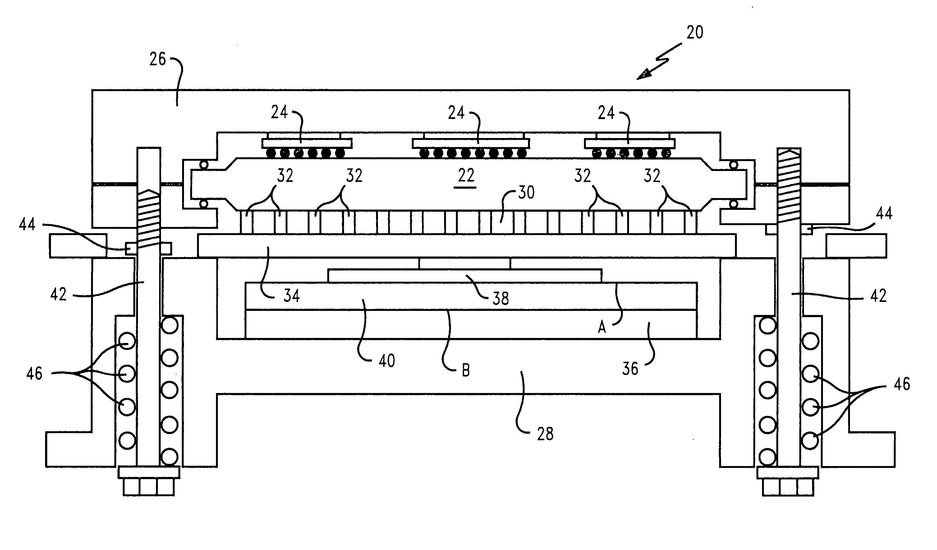
[0029] To provide a greater range of uniform or isostatic loading of the circuit board in an electronic module assembly, and in particular to connectors utilized therewith to connect to the integrated circuit board substrate, the present invention incorporates into the electronic module assembly an elastomeric layer between the circuit board in an electronic module assembly and the base member in the electronic module assembly. FIG. 1 illustrates a typical electronic module assembly incorporating the elastomeric structure of the present invention. Module assembly 20 includes a chip connection substrate 22 on which are mounted a plurality of integrated circuit chips 24, here shown as a 3×3 array. The individual integrated circuit chips may be connected by typical connection methods (not sho...


PUM


Abstract

An electronic module and a method of assembling the electronic module. A circuit board is connected to a chip substrate by an array of connectors, and a base member is on the side of the circuit board away from the chip substrate and connector array. An elastomeric structure is placed between the circuit board and the base member. The elastomeric structure has voids between a first defining plane adjacent the circuit board and a second defining plane adjacent the base member, with the voids adapted to permit local deformation of elastomeric material in the structure. The method includes applying a compressive force between the circuit board and base member to at least partially compressing the elastomeric structure to improve load equalization on the circuit board.

Description

BACKGROUND OF THE INVENTION [0001] 1. Field of the Invention [0002] The present invention relates to the manufacture of semiconductor devices and, in particular, to a system for ensuring uniform loading in semiconductor chip packaging. [0003] 2. Description of Related Art [0004] Integrated circuit chips are typically mounted in electronic module assemblies that provide electronic connection to the chip circuits, cooling as the chips operate, and mechanical protection for the chips. In such electronic modules assemblies, the integrated circuit chips are seated on and electrically connected to an electrical interconnect or interposer substrate which provides electrical connection between the chip circuit on one side, and a connector grid array which provides electrical connection to a circuit board. This connector grid array typically uses solder interconnection such as ball grid arrays (BGA), or column gird arrays (CGA) or non-solder contact land grid arrays (LGA) that require a forc...

Claims


Application Information

Patent Timeline
IPC IPC(8): H01L23/48
CPCH01L23/16H01L23/4093H01L24/72H01L2224/16H01L2224/73253H01L2924/01005H01L2924/01033H01L2924/14H01L2924/16152H01L2924/15787H01L2224/32014H01L2924/00
Inventor LONG, DAVIDBRODSKY, WILLIAMMILLER, JASONTOROK, JOHNZITZ, JEFFREY
Owner GLOBALFOUNDRIES INC
Features
  • R&D
  • Intellectual Property
  • Life Sciences
  • Materials
  • Tech Scout
  • Unparalleled Data Quality
  • Higher Quality Content
  • 60% Fewer Hallucinations
Learn More