Inductance device and manufacturing method thereof

a technology of inductance device and manufacturing method, which is applied in the direction of inductance, inductance with magnetic core, basic electric elements, etc., can solve the problems of difficult to avoid decreasing the efficiency (performance) of the coil, insufficient in view of workability, and air gap (clearance) that arises inevitably between the center core and the coil, etc., to achieve excellent productivity and low quality. , the effect of quality

Inactive Publication Date: 2007-03-08
YONEZAWA ELECTRIC WIRE
View PDF5 Cites 37 Cited by
  • Summary
  • Abstract
  • Description
  • Claims
  • Application Information

AI Technical Summary

Benefits of technology

[0015] The present invention has been carried out in view of the above-mentioned circumstances, and offers an inductance device which can be manufactured so that disparity of quality becomes low, in which the air gap between the core and the coil can be eliminated, and productivity is excellent. The present invention also offers a manufacturing method thereof.

Problems solved by technology

However, in method (1), when the hollow center coil is inserted into the center core, it is difficult for the hollow center coil to be attached exactly to the outer periphery (side surface) of the center core, so that there is a problem in which an air gap (clearance) tends to inevitably arises between the center core and the coil.
Therefore, it is difficult to avoid decreasing the efficiency (performance) of the coil due to the air gap.
Moreover, in order to manufacture the coil with the core, two processes of the manufacturing process of the hollow center coil and the insertion process for the center core are needed, which is inadequacy in view of workability.
Therefore, it is difficult to avoid decreasing the efficiency (performance) of the coil due to the air gap.
Moreover, because a core which consists of ferrite is very fragile and easily broken, careful handling is required, and a problem occurs in which productivity or yield is decreased.
However, in order to perform the press powder molding of the core, it is necessary to perform the press molding at considerably high temperature and high pressure.
Therefore, a problem occurs in which manufacturing equipment becomes large in size, and expense and cost increase.
When a powder pressing process is included in the manufacturing method of the inductance device, performing press molding of a formation including the magnetic powder and the binder with high temperature and high pressure may cause quality of the inductance device to change, and disparity of quality of the product to become higher.
It is, therefore, difficult to manufacture products of which disparity of quality is small and precision is high, and thereby a problem occurs in which yield is decreased and cost is increased.

Method used


Image

  • Inductance device and manufacturing method thereof
  • Inductance device and manufacturing method thereof
  • Inductance device and manufacturing method thereof

Examples


first embodiment

[0039] the present invention will be explained with reference to the figures.

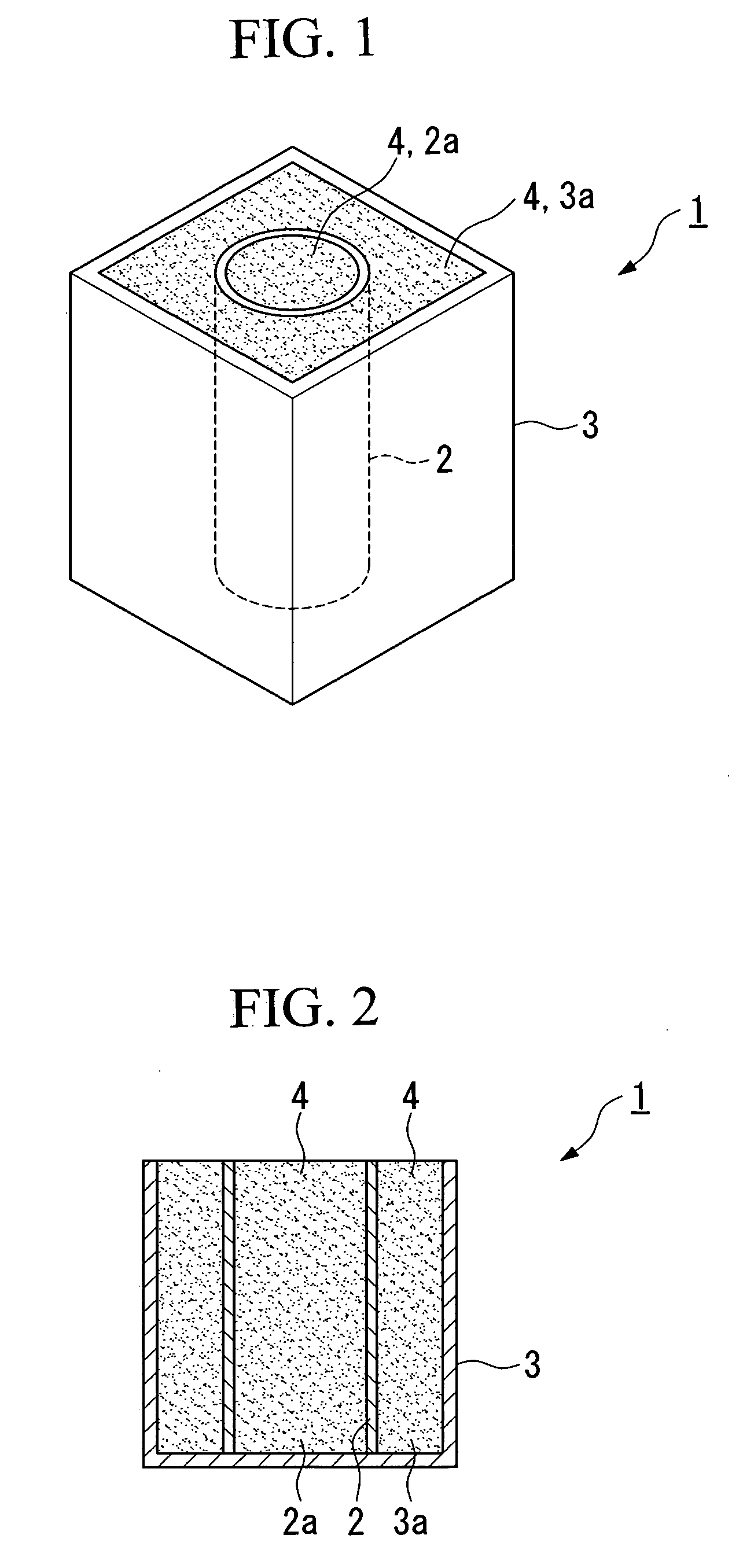
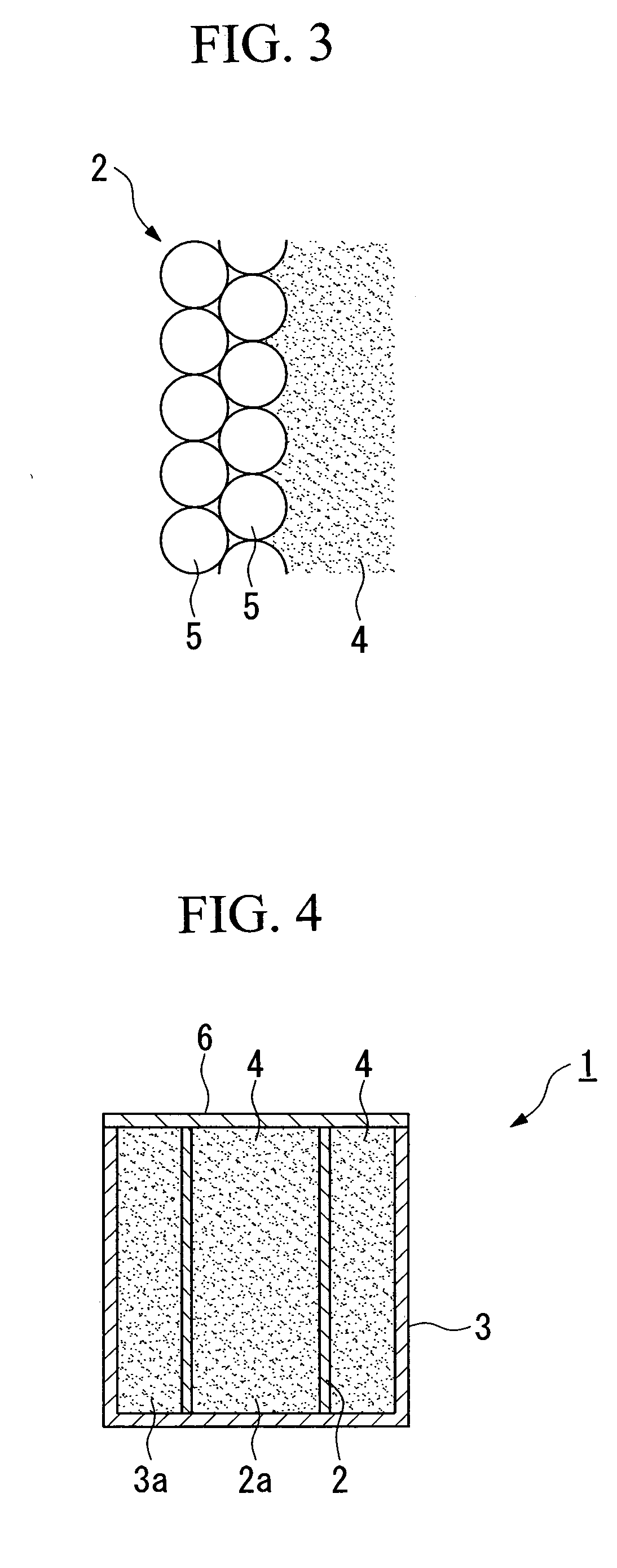
[0040] As shown in FIG. 1 and FIG. 2, in a choke coil (inductance device) 1 of the present invention, a hollow core coil 2 is arranged in a side case (accommodation case) 3 which is made of magnetic material. Filler 4 which is magnetic powder or a compound including the magnetic powder is filled into a hollow portion 2a of the hollow core coil 2 and the side case 3.

[0041] The hollow core coil 2 may be formed by winding a conducting wire so that the hollow portion 2a is formed along a center axis line, and the hollow core coil 2 may be formed as a bottomed shape, a tetragonal cylindrical shape, or any other shape. The center axis line of the hollow core coil 2 is not limited to a straight line, and may be a curved line such as an S-shaped line, or the like.

[0042] If necessary, both terminals of the conducting wire which constitutes the hollow core coil 2 may be connected to terminal portions (not shown in ...

second embodiment

[0050] Next, the present invention will be explained with reference to the figures.

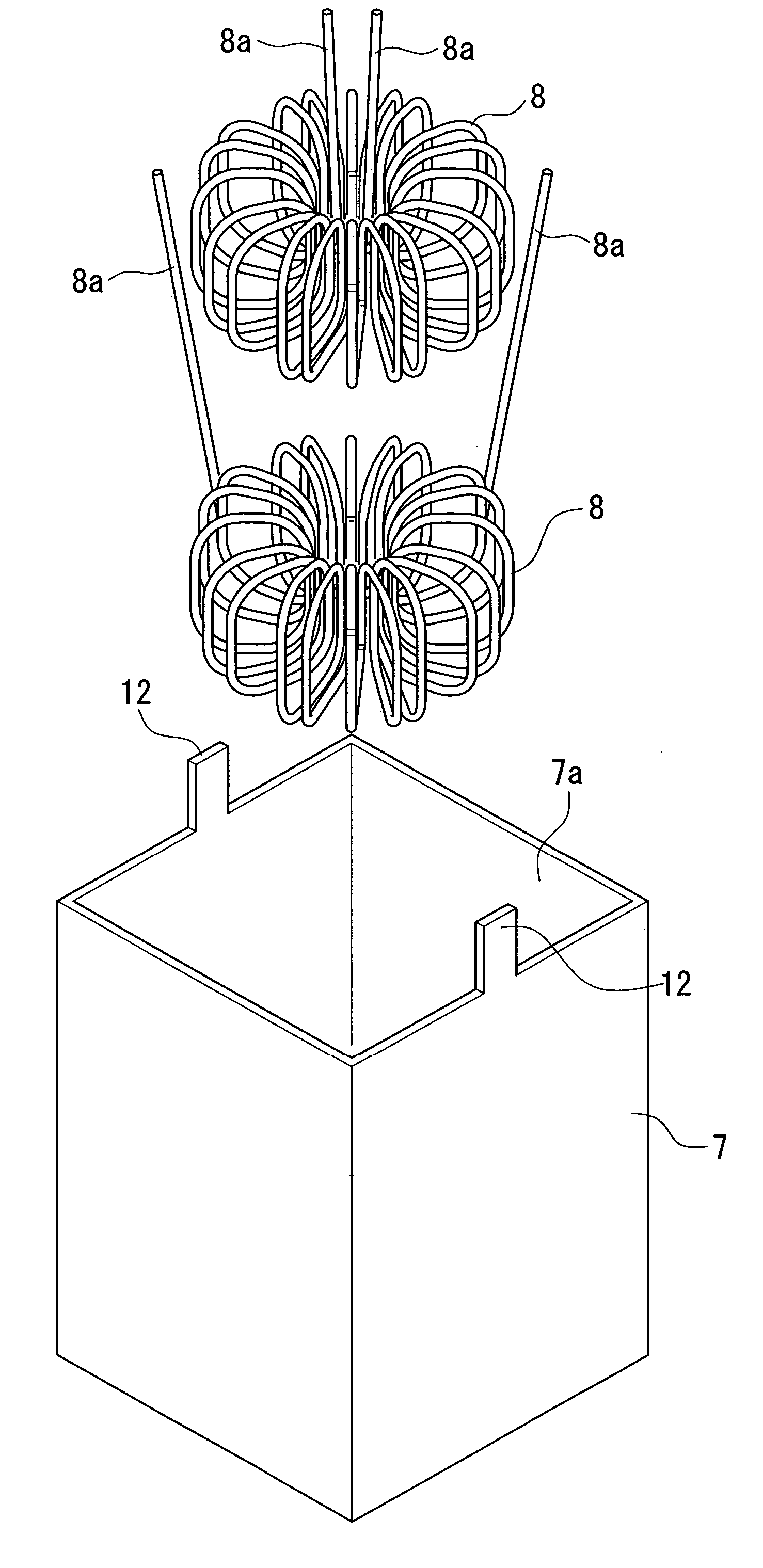
[0051] As shown in FIGS. 8 and 9, an inductance device 10 according to the present embodiment is provided with a metal case 7 (accommodation case) (hereinafter, occasionally, it is merely described as “case”), and hollow core coils 8 which are accommodated in this case 7. Furthermore, magnetic powder (filler) 9 is filled into the case 7.

[0052] The metal case 7 has a bottomed shape (rectangular shape) which has a bottom and has an opening portion toward an upper part. The opening portion 7a of the case 7 is sealed by a sealing material such as a copper laminated plate, potting material, a metal plate, an insulative substrate, or the like.

[0053] A plurality of tongue pieces 12 project from an edge of the opening portion 7a of the case 7. As shown in FIG. 8, the tongue pieces 12 are bent toward an inside of the opening portion 7a of the case 7, and the tongue pieces 12 press the sealing material 11, th...


PUM

PropertyMeasurementUnit
thicknessaaaaaaaaaa
diameteraaaaaaaaaa
inductanceaaaaaaaaaa

Abstract

An inductance device has a hollow center coil around which a conducting wire is wound so that a hollow portion is formed along a center axis line of the hollow center coil, a filler which is filled into the hollow portion of the hollow center coil, and includes magnetic powder or a compound including the magnetic powder, and an accommodation case which accommodates the hollow core coil and has a bottom, wherein the filler is filled into the accommodation case.

Description

BACKGROUND OF THE INVENTION [0001] 1. Field of the Invention [0002] The present invention relates to an inductance device which is properly used as a choking coil, an inductor, or the like, and a manufacturing method thereof. [0003] 2. Description of Related Art [0004] Conventionally, as a choking coil, art is known in which a coil is wound around a center core (drum core) which is composed of a magnetic material such as a ferrite, or the like, and a side case (accommodation case) is arranged around the center core (see, for example, Patent Document 1: Japanese Unexamined Patent Application, First Publication No. H10-199730, Patent Document 2: Japanese Unexamined Patent Application, First Publication No. H10-241969, Patent Document 3: Japanese Unexamined Patent Application, First Publication No. 2000-150244, Patent Document 4: Japanese Unexamined Patent Application, First Publication No. 2001-35723, and Patent Document 5: Japanese Unexamined Patent Application, First Publication No....

Claims


Application Information

Patent Timeline
Patent Type & Authority Applications(United States)
IPC IPC(8): H01F27/02
CPCH01F17/06H01F27/022H01F2017/048H01F41/005H01F27/027
Inventor SAEGUSA, SEIICHIRONAKAYA, HITOKIOCHI, TAKAYUKI
Owner YONEZAWA ELECTRIC WIRE
Why Eureka
Try Eureka