

Method for limiting transfer of material between two adjacent polymeric articles
a polymer and additive technology, applied in the field of limiting the transfer of a material between two adjacent polymeric articles, can solve the problems of insufficient lubricity, large amount of transferred additive contaminating the second article, and undesirable transfer of additives
- Summary
- Abstract
- Description
- Claims
- Application Information
AI Technical Summary
Benefits of technology
Problems solved by technology
Method used
Image

Examples
example 1
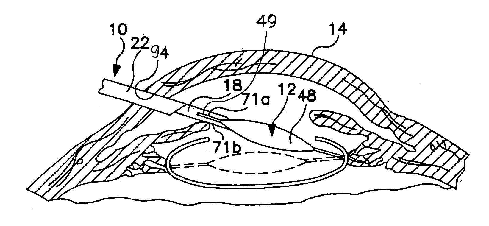
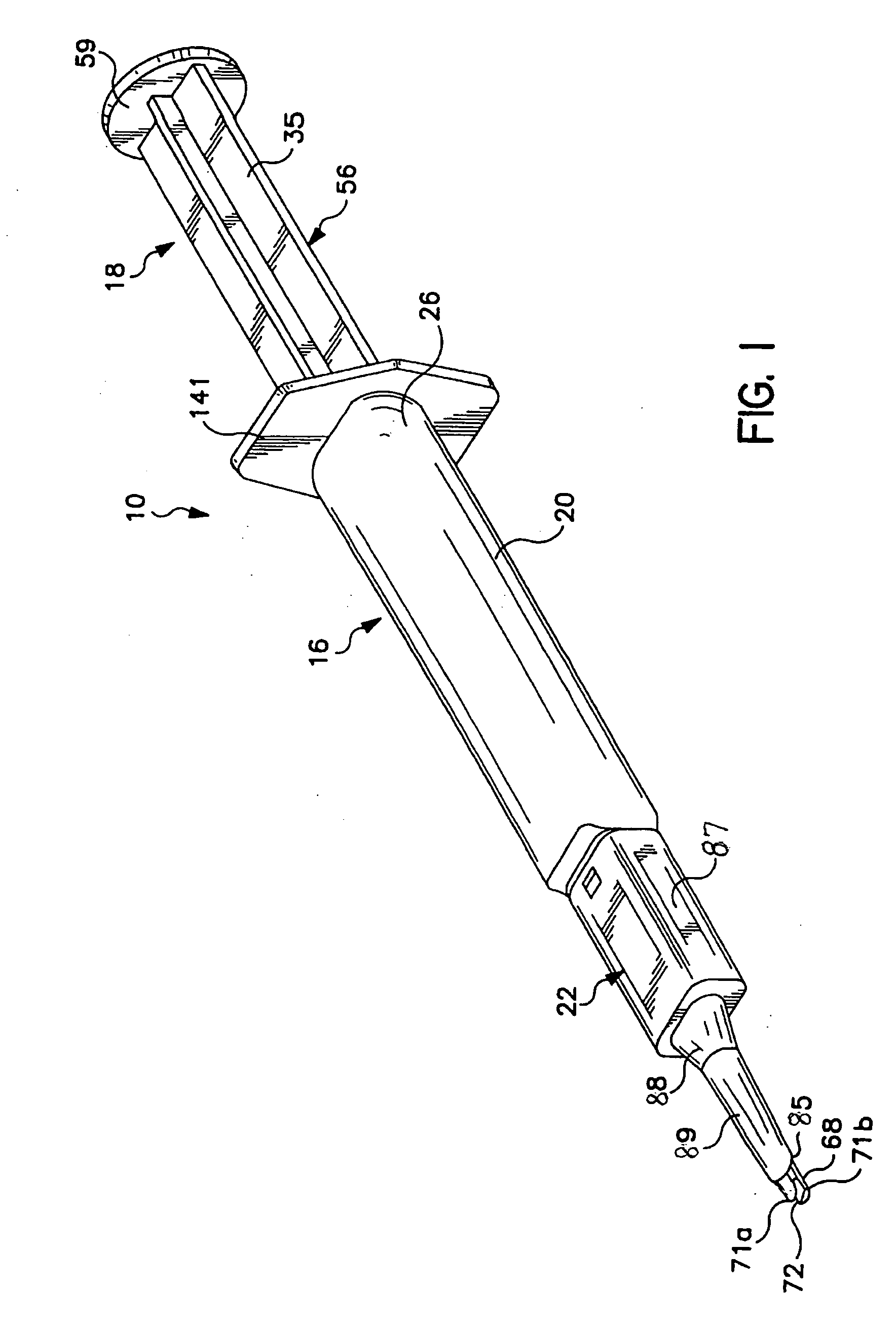
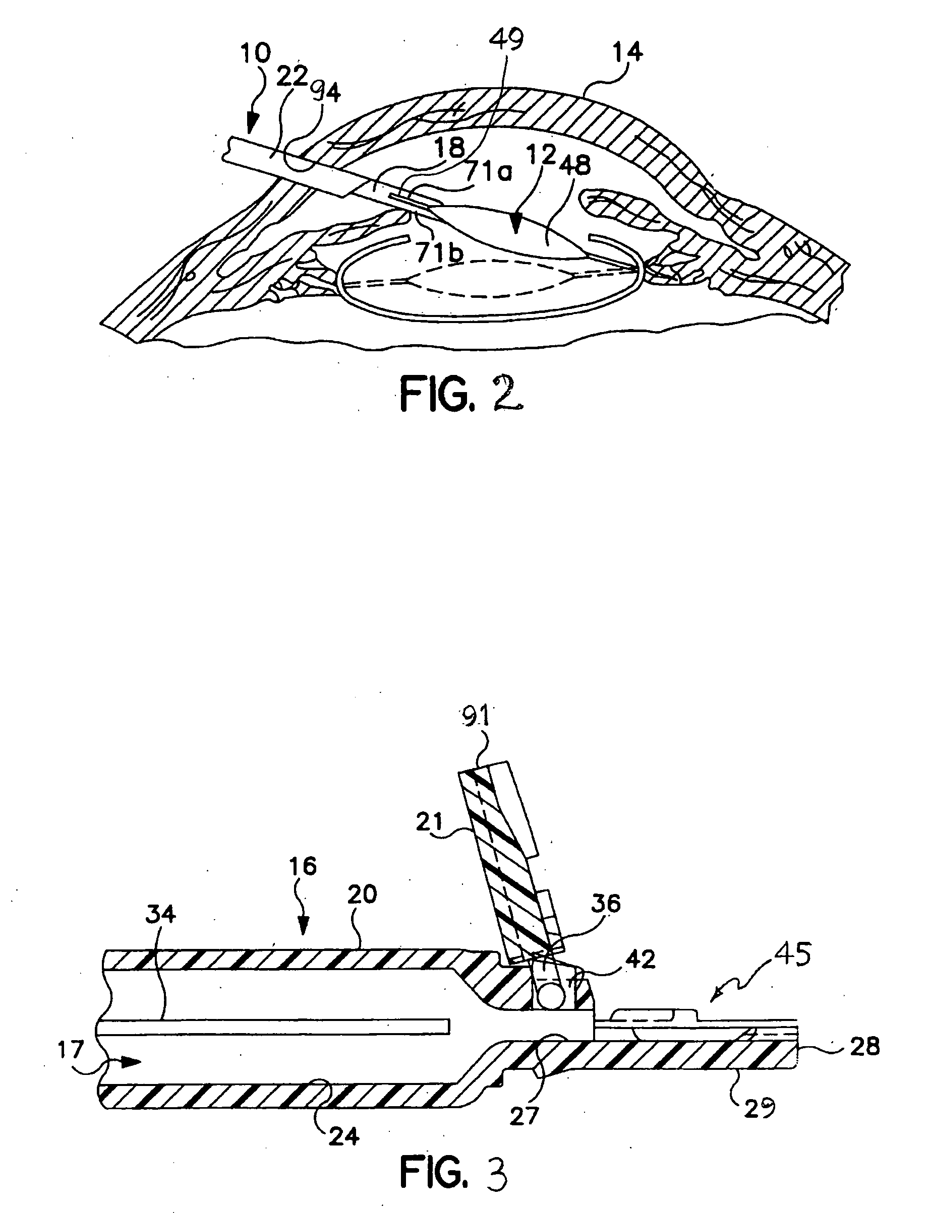
[0055] Components of inserters of the type illustrated in FIGS. 1 and 3-6 were made from a compounded material comprising polypropylene and glycerol monostearate (about 1 weight percent of the compounded material). A batch of cannulas was heat-treated at about 45° C. in a forced-convection oven. Another batch of cannulas was not heat-treated but subjected to a sterilization procedure at 50° C. for 24 hours (with or without exposure to ethylene oxide (“EO”)), to serve as control samples. Heat-treated cannulas were removed from the oven on day 3, 6, and 7, and complete inserters were assembled with these and untreated cannulas. The completely assembled inserters were tested for the transfer of the additive material from the cannulas to Adapt™ IOLs (Bausch and Lomb Incorporated, Rochester, N.Y.) after they were forced through the cannulas with the aid of Amvisc Plus™ viscoelastic material (Bausch and Lomb Incorporated, Rochester, N.Y.) disposed in the cannulas. Each IOL, after passing ...
example 2
[0058] Components of inserters of the type illustrated in FIGS. 1 and 3-6 were made from a compounded material comprising polypropylene and glycerol monostearate (about 1 weight percent of the compounded material). The components were subjected to a sterilization procedure using EO at 50° C. for 24 hours. Sterilized cannulas were allowed to age naturally at room temperature (control samples). Some cannulas were heat-treated at 45° C. for 3 and 7 days in a forced-convection oven after natural aging for 5 weeks. Other cannulas were heat-treated at 45° C. for 7 or 14 days in a forced-convection oven after natural aging for 8 weeks. Complete inserters were assembled with heat-treated and naturally aged cannulas of approximately same age and tested for the delivery of Adapt AO™ IOLs (Bausch and Lomb Incorporated, Rochester, N.Y.) with the aid of Amvisc Plus™ viscoelastic material (Bausch and Lomb Incorporated, Rochester, N.Y.) disposed in the cannula. Each IOL, after passing through the ...
example 3
[0063] Inserter components were made as disclosed in Example 2. Cannulas were heat-treated at 45° C. for 7 days substantially immediately after they were made and then sterilized with EO at 50° C. for 24 hours. Complete inserters were tested as in Example 2, and the results of the testing are shown in Table 7. Again, the amounts of transferred additive were observed to be much reduced.
TABLE 7Results of Testing of Cannulas Heat-Treated Then EO-SterilizedLens PowerTreatmentAmount ofLocation ofLens No.(diopters)MethodAdditiveAdditive1+10.045° C., 7 daysLO2+10.045° C., 7 daysLO3+10.045° C., 7 daysLO4+10.045° C., 7 daysLO5+10.045° C., 7 daysLO6+20.045° C., 7 daysLO7+20.045° C., 7 daysLO8+20.045° C., 7 daysLO9+20.045° C., 7 daysLO10+20.045° C., 7 daysLO11+30.045° C., 7 daysLO12+30.045° C., 7 daysLO13+30.045° C., 7 daysLO14+30.045° C., 7 daysLO15+30.045° C., 7 daysnoneno data
[0064]
PARTS LISTPart No.Description 10inserter 12IOL 14eye 16tubular member 17passage 18plunger 20base member 21co...
PUM
| Property | Measurement | Unit |
|---|---|---|
| temperature | aaaaa | aaaaa |
| temperature | aaaaa | aaaaa |
| temperature | aaaaa | aaaaa |
Abstract
Description
Claims
Application Information