Navigation system using both GPS and laser reference

a technology of laser reference and navigation system, which is applied in the direction of reference lines/planes/sectors, using reradiation, instruments, etc., can solve the problems of significant loss of satellite reception, slow down the operation of the positioning system, and lose sight of a number of satellites, so as to improve the accuracy of positioning system operation, improve the accuracy of positioning system, and improve the effect of positioning system operation

Active Publication Date: 2007-03-08
TRIMBLE NAVIGATION LTD
View PDF19 Cites 39 Cited by
  • Summary
  • Abstract
  • Description
  • Claims
  • Application Information

AI Technical Summary

Benefits of technology

[0007] Since the position of the machine is determined in part with regard to the laser transmitter, it is important for the positioning system to determine the position of the laser transmitter in the same coordinate system as that in which the positioning system operates when under global navigation satellite system control. While it is possible to determine in advance the position of the laser transmitter using manual surveying techniques, it will be appreciated that this may slow down the operation of the positioning system and present opportunities for errors to be made, as well.
[0008] The present invention contemplates a combination laser system and global navigation satellite positioning system that allows a user to realize high precision control of mobile units, including high precision machine control, without necessitating an extensive set up procedure. The positioning system comprises a laser transmitter, an optical sensor, a GPS receiver, and a device receiving and utilizing the signals from the optical sensor and the GPS receiver. The laser transmitter projects at least one laser beam that rotates about a generally vertical axis. The GPS receiver, including a GPS antenna, determines the position of the antenna. The optical sensor may be coaxial with, or displaced a small distance from, the phase center of the GPS antenna. Alternatively the optical sensor may be simply positioned a fixed position with respect to the phase center of the GPS antenna. The optical sensor receives the laser beam. The device receives signals from the GPS receiver and signals from the optical sensor to determine the position of the transmitter. Thereafter, the device utilizes signals received from the optical sensor to improve the estimate of position based on the signals from the GPS receiver. This positioning system may determine the position of a machine and then be used for controlling the machine by providing a control signal. The GPS data and the optical sensor data may advantageously be combined in a Kalman filter.
[0009] Accordingly, it is an object of the present invention to provide a system for determining the position of a machine and controlling the machine in which the operation of the system is facilitated.

Problems solved by technology

For example, if a motorgrader is about to travel under an overpass, it can be anticipated that the motorgrader system will lose sight of a number of the satellites.
Since global navigation satellite systems operate with the receiver receiving on a line-of-sight basis, it should be anticipated that there will be a significant loss of satellite reception.
While it is possible to determine in advance the position of the laser transmitter using manual surveying techniques, it will be appreciated that this may slow down the operation of the positioning system and present opportunities for errors to be made, as well.

Method used


Image

  • Navigation system using both GPS and laser reference
  • Navigation system using both GPS and laser reference
  • Navigation system using both GPS and laser reference

Examples


Embodiment Construction

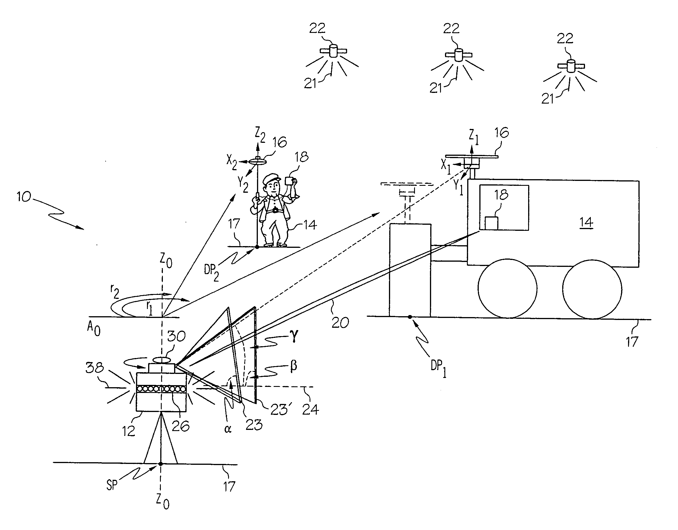
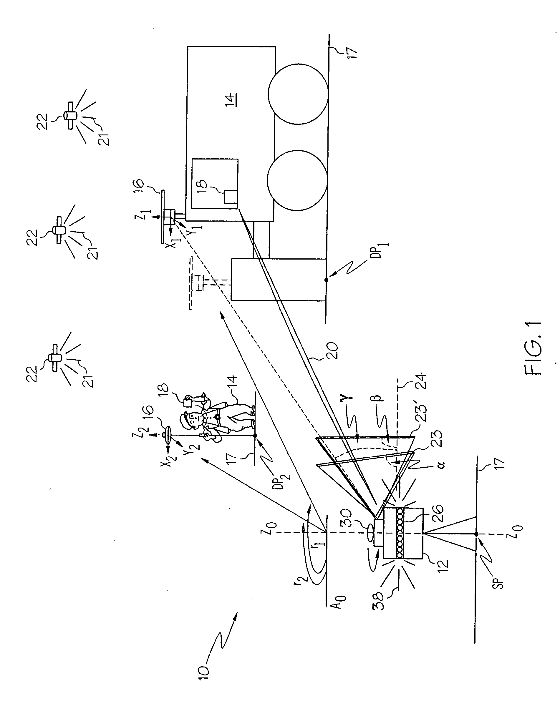
[0016] The present invention can be best understood by reference to FIG. 1 which depicts a position tracking and control (PTC) system 10. The PTC system 10 comprises a laser transmitter system 12, one or more mobile or rover units 14, each having a combination laser detector and global navigation satellite (CLDGNS) antenna 16 and an associated control system 18, and having a transmitter for establishing a communication link 20, preferably a radio link. Signals 21 from a plurality of global navigation satellites 22 orbiting the earth, such as GPS, GLONASS, GALILEO, and combinations thereof, are received by the CLDGNS antenna 16 so that the coordinates of dynamic points in a plot of land 17, such as points indicated as DP1, and DP2, can be determined to a centimeter level of accuracy by the control system 18. Control system 18 includes a microprocessor or other computing hardware configured to process data from the antenna 16 to provide an estimate of the position of the antenna 16.

[...


PUM


Abstract

A machine control system uses a laser system and global navigation satellite system to determine the position of the machine. The laser system has a laser detector positioned in a known and fixed relationship with the nominal phase center of a global navigation satellite antenna. The laser detector receives laser light transmitted from a laser transmitter. The outputs of the laser system and the global navigation satellite system are used together to determine the position of the transmitter prior to being used to determine the position of the machine.

Description

CROSS-REFERENCE TO RELATED APPLICATIONS [0001] This is a continuation-in-part of copending U.S. patent application Ser. No. 10 / 890,037, filed Jul. 13, 2004.STATEMENT REGARDING FEDERALLY SPONSORED RESEARCH OR DEVELOPMENT [0002] Not applicable. BACKGROUND OF THE INVENTION [0003] The current invention relates to position tracking and machine control systems and, in particular, to a combination of a laser system and a global navigation satellite system to track the position of a machine and to provide accurate control of the machine based on the tracking information. [0004] Global navigation satellite systems (hereinafter collectively referred to as GNSS), like GPS, and GLONASS, have been used extensively to determine position coordinates. Such position coordinates can be used in surveying operations, and for automated control of mobile units. In the future, the European GALILEO system will have similar capabilities. An autonomous navigational system that includes a satellite receiver a...

Claims


Application Information

Patent Timeline
Patent Type & Authority Applications(United States)
IPC IPC(8): G01C1/00G01B11/14G01S5/14G01S19/04G01S19/10G01S19/44G01S19/45
CPCE02F3/842E02F9/2045G01S19/45G01S17/023G01C15/004G01S17/86
Inventor TAYLOR, ARTHURTALBOT, NICHOLAS C.
Owner TRIMBLE NAVIGATION LTD
Why Eureka
Try Eureka