Remote display system and method

a display system and remote display technology, applied in the field of remote display systems, can solve problems such as data loss on the network, packet loss, delay, or change of the order of arriving packets, and significant degradation of reproducing/displaying quality, so as to improve the quality of a focused area

Inactive Publication Date: 2007-03-08
CANON KK
View PDF7 Cites 9 Cited by
  • Summary
  • Abstract
  • Description
  • Claims
  • Application Information

AI Technical Summary

Benefits of technology

[0015] The present invention provides a remote display system that significantly improves quality of a focused area while maintaining real-time characteristics by setting error resilience strength in accordance with a display state to each area of a screen.

Problems solved by technology

When the RTP protocol is used for transmission, a data loss on a network is a problem.
Due to abnormal routing paths or disturbances in a network, packet losses, delays, or changed order of arriving packets may occur.
This causes phenomena such as a sudden stop of moving images and a deformation of part of a screen, leading to significant degradation of reproducing / displaying quality.
In the above conventional examples, however, there is a problem in that image quality and real-time are not compatible with each other.
In the conventional examples (1) and (3), a large amount of buffering is needed to ensure an arrival wait time of are transmitted packet and thus, there is a disadvantage of significantly impairing real-time characteristic of display.
In the conventional example (2), there is a problem in that, since a bandwidth in proportion to the error resilience strength is required, image quality is degraded if the error resilience is enhanced when the bandwidth remains constant.
For example, while losses or screen deformations in units of lines or frames occur rarely, there are cases in which block noise, mosquito noise, or the like increases.
In the conventional example (4), there is a problem in that image quality is uniformly determined by the type of stream provided by the server and there is no room for further improvement of image quality.
In the conventional example (5), there is a problem in that the method is applicable only to hierarchically coded data.

Method used


Image

  • Remote display system and method
  • Remote display system and method
  • Remote display system and method

Examples


first exemplary embodiment

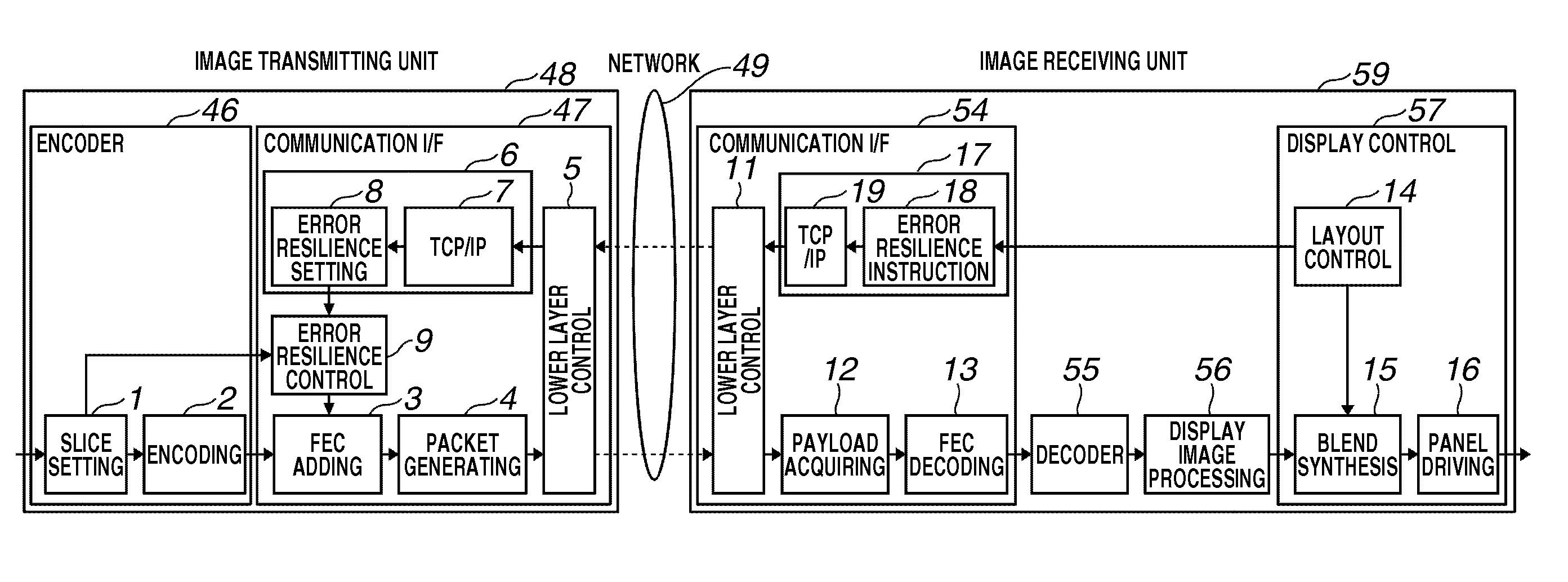
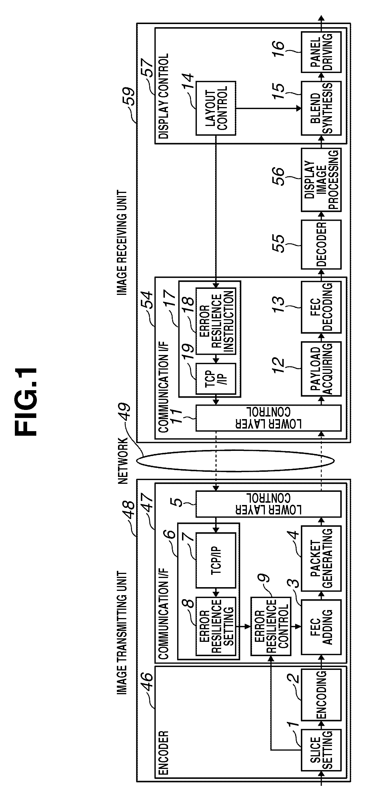
[0038] A remote display system in the present exemplary embodiment connects a server and a display terminal in one-to-one relation. The remote display system detects a display layout situation in each area of the content screen and lowers the error resilience strength for areas transparently overlapped or hidden by other objects.

[0039]

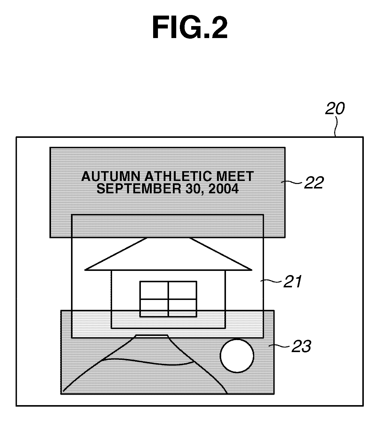
[0040]FIG. 2 will be used to describe an example of the display screen on the display terminal. The display terminal in the present exemplary embodiment displays a plurality of image contents in multi-window display. Each of image contents can be displayed in a window form while it is placed in an arbitrary location within the display area in an arbitrary size. If a window interferes with other windows or objects, the window is hidden behind other windows or overlapping is performed with some transparency. In FIG. 2, reference numerals 21-23 denote windows for displaying image content. The window 21 displays streaming content transmitted from a networ...

second exemplary embodiment

[0070] In the previous exemplary embodiment, a case is described in which a server and a display terminal are connected in one-to-one relation. In the present exemplary embodiment, a case is described in which a plurality of display terminals are connected to a server and data is delivered in multicasting. The server aggregates setting demands of each terminal and the error resilience strength of image areas that show a low level of importance among all terminals, is lowered.

[0071]

[0072] The block diagram in FIG. 8 will be used to describe the structure of a remote display system in the present exemplary embodiment. The same components as those in the previous exemplary embodiment are denoted by the same numbers and their descriptions are not repeated.

[0073] In FIG. 8, the network camera server 40 delivers data of captured images, in multicasting. Each of display terminals 82-85 has the same structure as the display terminal 50 in the previous exemplary embodiment. Multicast conte...

third exemplary embodiment

[0085] In the previous exemplary embodiment, an area is divided in units of slices of the encoder. In the present exemplary embodiment, an area is divided in arbitrary shapes in units of macro blocks.

[0086]

[0087] Block diagrams in FIGS. 13 and 14 will be used to describe the structure of an image transmission unit of a remote display system in the present exemplary embodiment. The same components as the previous exemplary embodiments are denoted by the same numbers and their descriptions are not repeated.

[0088]FIG. 13 is a block diagram showing the structure of an image transmitting unit in the present exemplary embodiment.

[0089] In the encoder 46, reference numeral 2 denotes an encoding unit. In the present exemplary embodiment, the procedure of Motion-JPEG is taken for encoding, and data is output to a communication interface with respect to each macro block. In the encoding unit 2, an orthogonal transform unit 131 performs a discrete cosine transform (DCT) operation, a quantiz...


PUM


Abstract

A remote display system having a server to transmit moving image content data to a network, and a display terminal to receive and reproduce / display the image data, transmits the image data to which an error resilience code is attached, displays the image content together with other display elements on the display terminal, determines a display shape of the image content in the display, and changes an error resilience method in accordance with a result of the display shape determination.

Description

BACKGROUND OF THE INVENTION [0001] 1. Field of the Invention [0002] The present invention relates to an image forming apparatus and a control method thereof, a computer program, and a computer readable storage medium. [0003] 2. Description of the Related Art [0004] A VOD (Video On Demand) streaming system and a network monitoring system have been known as an apparatus for displaying / reproducing remote moving image content via a network. In the VOD streaming system, content stored on a remote server is viewed on a personal computer connected to a network. In the network monitoring system, an image taken by a remote monitoring camera is displayed on a personal computer or a dedicated monitor connected to a network for monitoring. [0005] These systems are constructed by connecting a storage server or camera server with a personal computer or display terminal apparatus via a network. In order to view the image on a personal computer, various kinds of software such as an application for ...

Claims


Application Information

Patent Timeline
Patent Type & Authority Applications(United States)
IPC IPC(8): H04N7/64H04N19/89
CPCH04N19/89H04N19/61
Inventor SUNAKAWA, SHINICHI
Owner CANON KK
Why Eureka
Try Eureka