Method and apparatus for maintaining high voltage in a fuel cell
Inactive Publication Date: 2007-03-08
TACTICAL FUEL CELLS
5 Cites 3 Cited by
AI-Extracted Technical Summary
Problems solved by technology
However, the global energy system is moving steadily away from the carbon-rich fuels whose combustion produces the harmful gas.
Furthermore, fossil fuels cause pollution and are a causative factor in the strategic military struggles between nations.
Furthermore, fluctuatin...
Method used
Groups 8, 9, 10, and 11 are comprised of multiple elements having multiple valency states. By including materials having mixed valency states, the elevated operating voltage is enabled.
[0032] To provide for the higher operating potential within the fuel cell, the fuel cell is reverse biased whereby an initial charging current is provided to the fuel cell to obtain the elevated operating voltage wherein the elevated operating voltage is above the normal operating voltage of the fuel cell, and a continual charging current is subsequently provided to the fuel cell to sustain the elevated operating voltage. The normal operating voltage of a fuel cell is herein defined as the operating voltage of the fuel cell achieved through normal operating conditions without a charging current being supplied to the fuel cell to charge the electrodes.
[0035] To sustain the increased operating potential, the continual charging current is provided to the fuel cell subsequent to the initial charging current. The continual charging current may be supplied to the fuel cell in a continuous or pulsing manner such that the operating potential of the fuel cell is not allowed to drop below a predetermined level. After recei...
Benefits of technology
[0019] Upon the fuel cell receiving the initial charging current or the continual charging current, hydrogen is evolved at the hydrogen electrode and/or oxygen is evolved at the oxygen electrode, wherein the evolved hydrogen is absorbed by the hydrogen electrode and/or the evolved oxygen is absorbed by the oxygen electrode. The hydrogen electrode may comprise a hydrogen storage material which provides for the storage of hydrogen. The oxygen electrode may c...
Abstract
A method and apparatus for elevating the operating voltage in a fuel cell having a hydrogen electrode with hydrogen storage capacity and/or an oxygen electrode with oxygen storage capacity. The fuel cell is able to sustain the elevated voltage through application of an electrical current to the fuel cell resulting in the charging of the hydrogen electrode and/or the oxygen electrode.
Application Domain
Reactant parameters controlCell electrodes +2
Technology Topic
High pressureHigh voltage +6
Image
Examples
- Experimental program(1)
Example
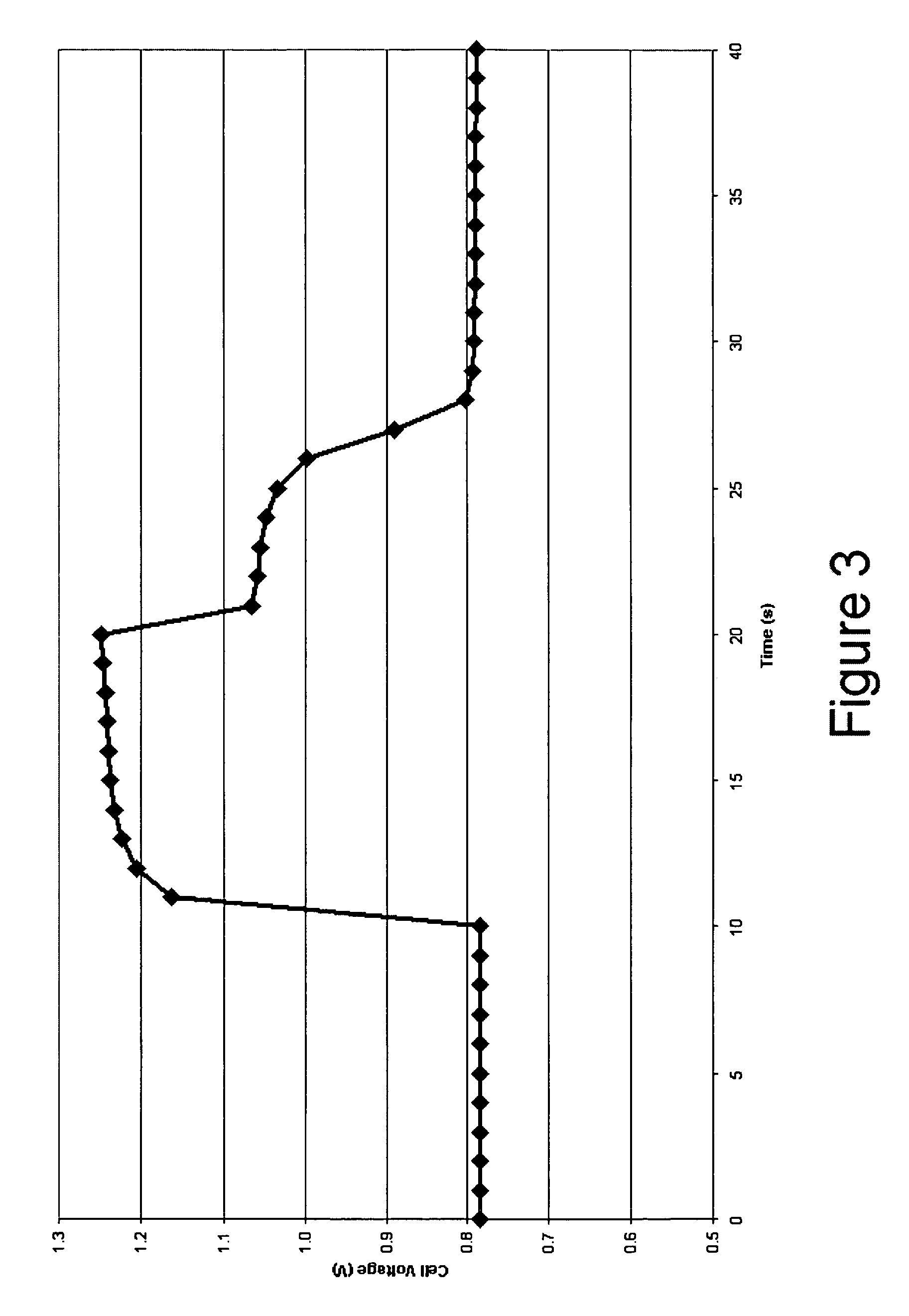
[0025] In accordance with the present invention there is provided a method for achieving and sustaining a higher operating potential resulting in increased voltage in a fuel cell having energy storage capability. An alkaline fuel cell having a hydrogen electrode with hydrogen storage capability and an oxygen electrode with oxygen storage capability may have a normal operating cell voltage of approximately 0.75V. As shown in FIG. 3, by applying a 100 mA/cm2 pulse of electrical current to the alkaline fuel cell, the fuel cell operating voltage increases to over 1.2 volts. By applying the techniques of the present invention the cell voltage of the alkaline fuel cell is able to be sustained well above the normal operating cell voltage. Preferably, the alkaline fuel cell sustains an elevated operating voltage above 0.9 volts. More preferably, the alkaline fuel cell sustains an elevated operating voltage above 1.0 volts. Most preferably, the alkaline fuel cell maintains an elevated operating voltage above 1.1 volts. By varying the amount of electrical current supplied to the fuel cell, the operating voltage of the fuel cell can also be tailored for different applications. The same principles applied to the alkaline fuel cell can be applied to other types of fuel cells such as PEM fuel cells, direct methanol fuel cells, solid oxide fuel cells, molten carbonate fuel cells, phosphoric acid fuel cells, zinc-air fuel cells, or proton ceramic fuel cells.
[0026] To acquire and maintain an elevated operating voltage, the fuel cell requires the ability to store a charge. To store a charge, the fuel cell requires the use of a hydrogen electrode providing for the storage of hydrogen and/or an oxygen electrode providing for the storage of oxygen. While the fuel cell only requires a hydrogen electrode with hydrogen storage capacity or an oxygen electrode with oxygen storage capacity, it is preferable to use both a hydrogen electrode with hydrogen storage capacity and an oxygen electrode with oxygen storage capacity within the fuel cell.
[0027] The hydrogen electrode with hydrogen storage capacity may comprise an anode active material providing for the storage of hydrogen in metal hydride form. The anode active material may be deposited or supported on a current collector. The current collector may be selected from, but not limited to, an electrically conductive mesh, grid, foam, expanded metal, or combinations thereof. The active material of the hydrogen electrode is generally a hydrogen storage material optionally including a catalytic material. The preferable active material layer is one which can reversibly absorb and release hydrogen irrespective of the hydrogen storage capacity and has the properties of a fast hydrogenation reaction rate, a good stability in the electrolyte, and a long shelf-life. It should be noted that, by hydrogen storage capacity, it is meant that the material stores hydrogen in a stable form, in some nonzero amount higher than trace amounts. Preferred materials will store about 1.0 weight % hydrogen or more. Preferably, the alloys include, for example, rare-earth/Misch metal alloys, zirconium and/or titanium alloys, or mixtures thereof. The active material layer may even be layered such that the material on the hydrogen contacting surface of the active material layer is formed from a material which has been specifically designed to be highly catalytic to the dissociation of molecular hydrogen into atomic hydrogen, while the material on the electrolyte contacting surface is designed to be highly catalytic to the oxidation of hydrogen.
[0028] Certain hydrogen storage materials are exceptionally useful as alkaline fuel cell hydrogen electrode materials. The useful hydrogen storage alloys have excellent catalytic activity for the formation of hydrogen ions from molecular hydrogen and also have superior catalytic activity toward the formation of water from hydrogen ions and hydroxyl ions. In addition to having exceptional catalytic capabilities, the materials also have outstanding corrosion resistance toward the electrolyte of the fuel cell. In use, the alloy materials act as 1) a molecular hydrogen decomposition catalyst throughout the bulk of the hydrogen electrode; and 2) as an internal hydrogen storage buffer to insure that a ready supply of hydrogen atoms is always available at the electrolyte contacting surface.
[0029] When disposed in a fuel cell having an oxygen electrode with oxygen storage capacity, the hydrogen electrode may not require an active material with hydrogen storage capacity. In such cases, the hydrogen electrode may be any type electrode known in the art for use in alkaline fuel cells, PEM fuel cells, direct methanol fuel cells, solid oxide fuel cells, molten carbonate fuel cells, phosphoric acid fuel cells, zinc-air fuel cells, or proton ceramic fuel cells.
[0030] The oxygen electrode may comprise a cathode active material including a redox couple material providing for the storage of oxygen via a valency change. The cathode active material may be deposited or supported on a current collector. The current collector may be selected from, but not limited to, an electrically conductive mesh, grid, foam, expanded metal, or combinations thereof. The redox couple material includes one or more redox couples which store oxygen via a change in valency when the redox couple material is oxidized from its reduced form. Numerous redox couples exist and may be used to form the cathode of this invention. When such couples are used, cycling transition from one valency state (the oxidized form) to another valency state (the reduced form) is accomplished repeatedly and continuously. From a practical point of view, the ability to withstand such cycling is preferred. While not wishing to be bound by theory, some of the redox couples that can be used in the oxygen electrode of the fuel cell of this invention are presented below.
Co+2←→Co+3 (Valency level 2 to a valency level 3) Co(OH)2+OH−→CoOOH+H2O+e− (1)
Co+2←→Co+4 (Valency level 2 to a valency level 4) Co(OH)2+2OH−→Co(OH)4+2e− Co(OH)4→CoO2+2H2O (2)
Ni+2←→Ni+3 (Valency level 2 to valency level 3) Ni(OH)2+OH−→NiOOH+H2O+e− (3)
Ni+2←→Ni+4 (Valency level 2 to valency level 4) Ni(OH)2+2OH−→Ni(OH)4+2e− Ni(OH)4→NiO2+2H2O (4)
Ag←→Ag+ (Valency level 0 to valency level 1) 2Ag+2OH−→Ag2O+H2O+e− (5)
Ag←→Ag+2 (Valency level 0 to valency level 2) Ag+2OH−→AgO+H2O+2e− (6)
Cu←→Cu+2 (Valency level 0 to valency level 2) Cu+2OH−→CuO+H2O+2e− (7)
(Ni/Ag)+2←→(Ni/Ag) (8)
(Ni/Fe)oxide+2←→(Ni/Fe)oxide+3 (9)
Mn+2←→Mn+3→Mn+7 (10)
Sn+2←→Sn+4 (11)
Groups 8, 9, 10, and 11 are comprised of multiple elements having multiple valency states. By including materials having mixed valency states, the elevated operating voltage is enabled.
[0031] When disposed in a fuel cell having a hydrogen electrode with hydrogen storage capacity, the oxygen electrode may not require an active material with oxygen storage capacity. In such cases, the hydrogen electrode may be any type electrode known in the art for use in alkaline fuel cells, PEM fuel cells, direct methanol fuel cells, solid oxide fuel cells, molten carbonate fuel cells, phosphoric acid fuel cells, zinc-air fuel cells, or proton ceramic fuel cells.
[0032] To provide for the higher operating potential within the fuel cell, the fuel cell is reverse biased whereby an initial charging current is provided to the fuel cell to obtain the elevated operating voltage wherein the elevated operating voltage is above the normal operating voltage of the fuel cell, and a continual charging current is subsequently provided to the fuel cell to sustain the elevated operating voltage. The normal operating voltage of a fuel cell is herein defined as the operating voltage of the fuel cell achieved through normal operating conditions without a charging current being supplied to the fuel cell to charge the electrodes.
[0033] The initial charging current and the continual charging current may comprise a continuous electric current having a specified duration, one or more electrical pulses, or a combination thereof. The duration of the electrical pulses may vary as needed for each application, and may range from nanoseconds to seconds. The rate at which the initial charging current and the continual charging current are supplied to the fuel cell depends on the type of fuel cell being used. The rate at which the initial charging current and the continual charging current are supplied to the fuel cell is preferably approximate to the rate at which the fuel cell is discharged. The initial charging current and the continual charging current may be supplied to the fuel cell at other rates provided the rates are compatible with the fuel cell.
[0034] As the initial charging current or the continual charging current is supplied to the fuel cell, hydrogen is evolved at the hydrogen electrode and/or oxygen is evolved at the oxygen electrode. The hydrogen storage material in the hydrogen electrodes absorbs the evolved hydrogen and forms a metal hydride thereby charging the hydrogen electrode and/or the redox material in the oxygen electrode absorbs the evolved oxygen and forms oxides thereby charging the oxygen electrode. Once the hydrogen electrode and/or the oxygen electrode is charged, an the operating voltage of the fuel cell is increased to an elevated operating voltage. As energy is discharged from the fuel cell, the metal hydride and the oxides formed by the electrical current being supplied to the fuel cell will be utilized as a source of hydrogen or oxygen resulting in their restoration to the original charge status. After at least a portion of the stored energy is removed from the electrode, the electrodes are once again ready to receive hydrogen and/or oxygen upon application of a charge current to the fuel cell. In such a case the operation of the fuel cell mimics the operation of a battery.
[0035] To sustain the increased operating potential, the continual charging current is provided to the fuel cell subsequent to the initial charging current. The continual charging current may be supplied to the fuel cell in a continuous or pulsing manner such that the operating potential of the fuel cell is not allowed to drop below a predetermined level. After receiving the initial charging current, the electrode is not allowed to discharge fully (its potential should not come down to its starting potential prior to applying the initial charging current). This concept is illustrated in FIG. 4, whereby an initial charging current is first applied to a fuel cell and a continual charging current is applied to the fuel cell thereafter not allowing the operating voltage of the fuel cell to drop below 1.0 volts. Since the fuel cell electrodes are not fully discharged, the continual charging current requires a smaller duration charge pulse than the initial charging current. The continual charging current should be of the same magnitude as the initial charging current to restore the electrode potential to the higher value. By repeating this process indefinitely, the overall fuel cell voltage can be maintained at a elevated value. In other words, the operating potential of the fuel cell is artificially kept at a elevated value by charging for slightly longer time and discharging for a lesser time. The charge pulse duration and the discharge pulse duration can be optimized based on the relative efficiencies of charging the hydrogen electrode and the oxygen electrode.
[0036] When the charge current is in the form of one or more electrical pulses, the charge to discharge pulse times may be around 80%. In other words the charge pulse will last slightly longer than the discharge pulse. The concept is unique since the pulse duration can be few seconds in the forward and backward direction. It is necessary not to push the potential of the electrodes so that they are irreversibly oxidized (metal hydride electrodes) or corroded heavily (air electrode).
[0037] By supplying the charging current to the fuel cell, the fuel cell may sustain an elevated operating voltage at least 10% above the normal operating voltage of the fuel cell. Preferably, the fuel cell sustains an elevated operating voltage at least 20% above the normal operating voltage of the fuel cell. More preferably, the fuel cell sustains an elevated operating voltage at least 30% above the normal operating voltage of the fuel cell. Most preferably, the fuel cell sustains an elevated operating voltage at least 40% above the normal operating voltage of the fuel cell.
[0038] The electrical current may be supplied to the fuel cell from one or more electrical power sources internal or external to the fuel cell. The electrical power sources may include one or more selected from batteries, solar cells, generators, regenerative braking, capacitors, power grid, and any other sources of an electrical current. The fuel cell may also have a feed back loop which continually provides the fuel cell with the charge needed to sustain the elevated operating voltage.
[0039] While there have been described what are believed to be the preferred embodiments of the present invention, those skilled in the art will recognize that other and further changes and modifications may be made thereto without departing from the spirit of the invention, and it is intended to claim all such changes and modifications as fall within the true scope of the invention.
PUM


Description & Claims & Application Information
We can also present the details of the Description, Claims and Application information to help users get a comprehensive understanding of the technical details of the patent, such as background art, summary of invention, brief description of drawings, description of embodiments, and other original content. On the other hand, users can also determine the specific scope of protection of the technology through the list of claims; as well as understand the changes in the life cycle of the technology with the presentation of the patent timeline. Login to view more.