
Method for estimating unknown parameters for a vehicle object detection system

a vehicle object and unknown parameter technology, applied in the field of unknown parameter estimation in the vehicle object detection system, can solve the problems of large amount of computation, lack of robust, accurate estimates, etc., and achieve the effect of efficiently solving the non-linear optimization problem and further simplifying the problem

Inactive Publication Date: 2007-03-08
APTIV TECH LTD
View PDF37 Cites 98 Cited by
  • Summary
  • Abstract
  • Description
  • Claims
  • Application Information

AI Technical Summary

Benefits of technology

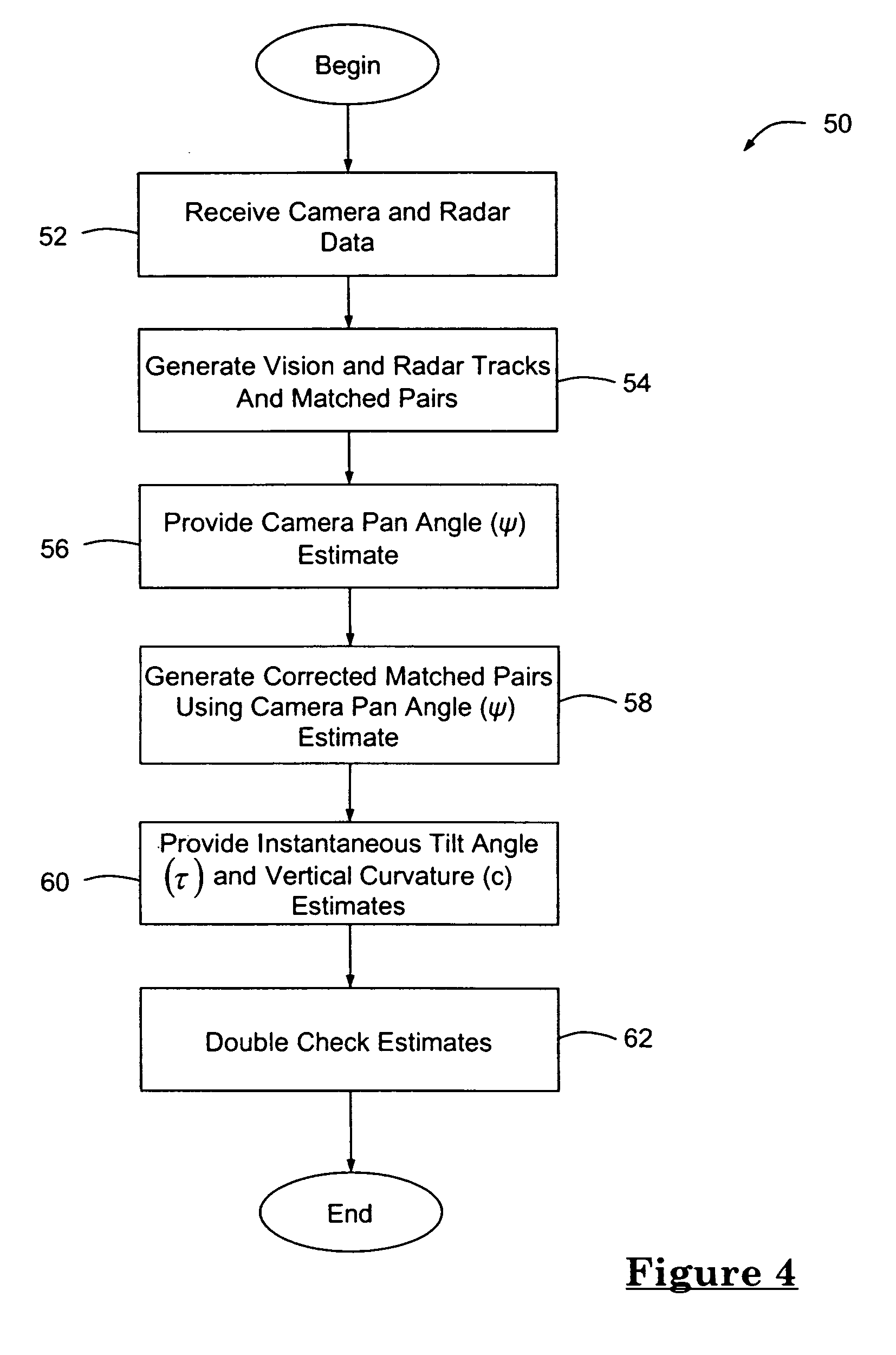
[0005] According to one aspect of the invention, there is provided a method for estimating unknown parameters for a vehicle object detection system. This method includes the steps of generating one or more vision and radar tracks, generating one or more matched pairs from the vision and radar tracks, and estimating a camera pan angle (ψ), an instantaneous tilt angle (τ) and / or the road geometry, wherein the estimates minimize the alignment error between the matched pair.
[0007] According to yet another aspect, the non-linear optimization problem is further simplified by linearization about the predicted values of the parameters. Furthermore, a least squares error criterion is chosen for the optimization metric resulting in a linear least squares problem that can be efficiently solved.
[0008] Objects, features and advantages of this invention include, but are certainly not limited to, providing more accurate and efficient pan angle, instantaneous tilt angle and vertical curvature estimates for a vehicle object detection system.

Problems solved by technology

These techniques, however, require a significant amount of computations and frequently do not produce robust, accurate estimates.

Method used


Image

  • Method for estimating unknown parameters for a vehicle object detection system
  • Method for estimating unknown parameters for a vehicle object detection system
  • Method for estimating unknown parameters for a vehicle object detection system

Examples


Embodiment Construction

[0016] The present method for estimating unknown parameters can be used with a number of different types of vehicle object detection systems, but is particularly well suited for use with forward looking, radar-cued vision systems (both monocular and stereo vision systems). Accordingly, the following description of the preferred embodiment is provided in the context of a forward looking, radar-cued vision system, even though the method of the present invention could be used with other types of object detection systems.

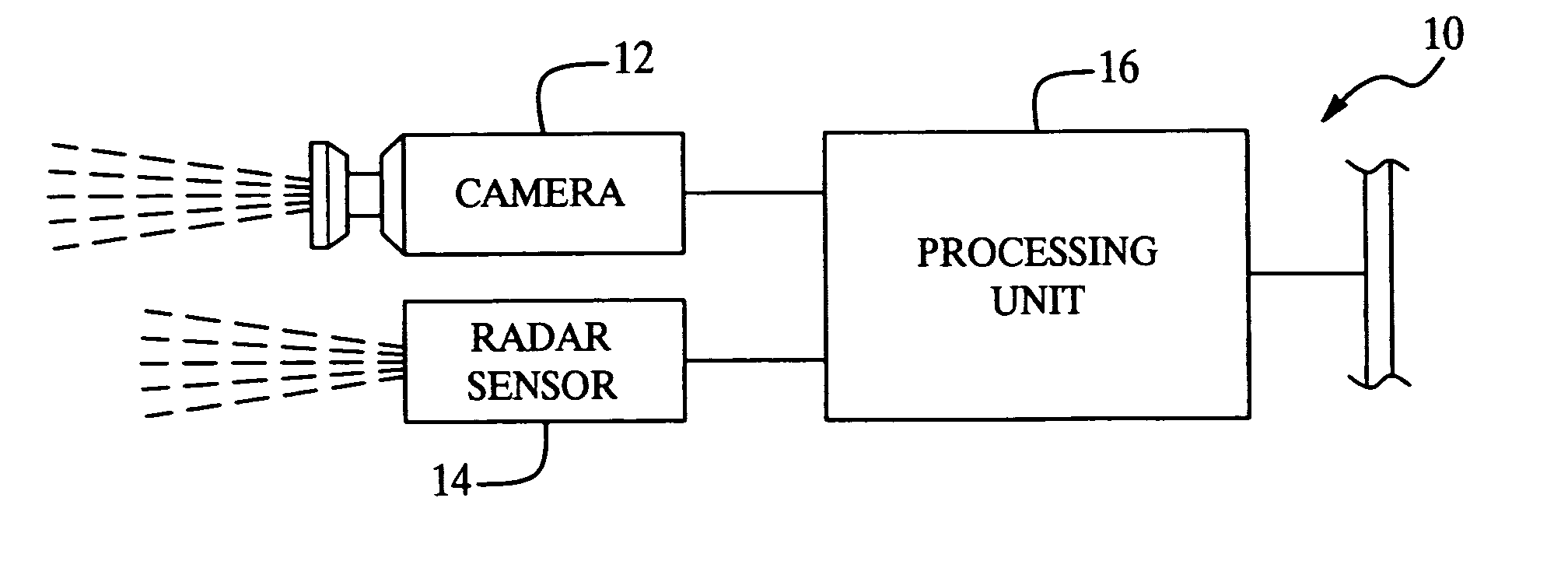
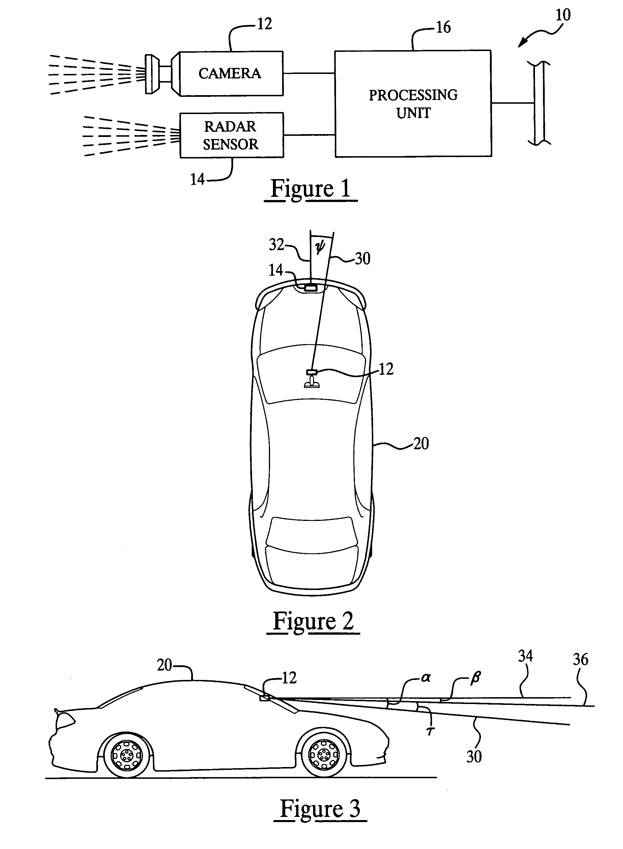
[0017] With reference to FIG. 1, there is shown a vehicle object detection system 10 of the forward looking, radar-cued monocular vision type that generally includes a camera 12, a radar sensor 14 and a processing unit 16 connected to the camera and the radar sensor. Of course, system 10 could include one of any number of additional components and could be connected to other systems, devices, networks, etc., such as a warning indicator on a vehicle instrument panel, a ...


PUM


Abstract

A method for estimating unknown parameters (pan angle (ψ), instantaneous tilt angle (τ) and road geometry of an upcoming road segment) for a vehicle object detection system. The vehicle object detection system is preferably a forward looking, radar-cued vision system having a camera, a radar sensor and an processing unit. The method first estimates the pan angle (ψ), then corrects the coordinates from a radar track so that pan angle (ψ) can be treated as zero, and finally solves a least squares problem that determines best estimates for instantaneous tilt angle (τ) and road geometry. Estimating these parameters enables the vehicle object detection system to identify, interpret and locate objects in a more accurate and efficient manner.

Description

TECHNICAL FIELD [0001] The present invention relates to a method for estimating unknown parameters in a vehicle object detection system, and more particularly, to a method for estimating camera pan and tilt angles and the geometry of an upcoming road segment. BACKGROUND OF THE INVENTION [0002] Various types of object detection systems for motor vehicles have been developed which utilize one or more sensors to identify, interpret and / or locate objects surrounding the vehicle. Examples of such systems include forward looking systems (FLS), rear detection systems (RDS), and side detection systems (SDS). [0003] Some FLSs are referred to as “vision-only systems,” in that they only utilize cameras and not radar, laser or other types of sensors. In the case of single camera vision systems (referred to as “monocular vision systems”) and multiple camera vision systems (referred to as “stereo vision system”) a processing unit usually has to estimate the pan and tilt angles of a camera, as wel...

Claims


Application Information

Patent Timeline
IPC IPC(8): G08G1/16G01S13/931
CPCG01S7/4026G01S13/931G01S2007/4091G01S13/867G01S2007/403G01S2013/9357G01S2013/9375G01S2007/4034G01S2013/9322G01S2013/93271G01S7/4034G01S7/403G01S7/4091
Inventor SCHIFFMANN, JAN K.SCHWARTZ, DAVID A.
Owner APTIV TECH LTD
Learn More