Method and Apparatus for Flushing a Container with an Inert Gas

a technology of inert gas and container, applied in the field of potable fluid bottling, can solve the problems of adding more time to reducing the efficiency of the overall packaging cycle, and not being useful in the application of the method for non-pressurized containers such as milk and juice bottles, so as to improve the reduction of oxygen, reduce equipment and space, and improve the effect of oxygen reduction

Inactive Publication Date: 2007-03-15
RUPPMAN KURT H SR +1
View PDF41 Cites 35 Cited by
  • Summary
  • Abstract
  • Description
  • Claims
  • Application Information

AI Technical Summary

Benefits of technology

[0007] In one example embodiment, a method is provided for extending shelf life of a potable liquid in a container sealed by a cap enclosing an opening of the container. The container and cap cooperate to define a head space above the potable liquid. One step of the method is flushing the container with an inert gas to reduce the oxygen level within the container to a first percentage lower than ambient air. Another step is filling the container with the potable liquid while the oxygen level in the container is maintained below that of ambient air. Another step is changing the relationship between the cap and opening from a first position to a second position, wherein a distance between the cap and opening is smaller at the first position than at the second position. Another step is introducing an inert gas toward the opening when the cap and opening are at the second position. Another step is sealing the cap on the container with the inert gas enclosed in the head space.

Problems solved by technology

However, this method is not useful for non-pressurized containers such as milk and juice bottles.
The snap-on caps for these containers are not designed to withstand the pressures developed by the vaporized nitrogen, and the increased pressure created by the vaporized nitrogen breaks the seal between the cap and bottle, allowing air to be sucked back into the container during handling and shipping, renewing microbial attack.
As a result, shelf life of non-pressurized capped containers is not significantly extended using this method.
The inerting step must be carried out as a separate step between filling and sealing the container, and therefore adds more time to the overall packaging cycle, which reduces throughput.
Also, the apparatus for positioning, operating and removing the nozzle is complex and relatively expensive.

Method used


Image

  • Method and Apparatus for Flushing a Container with an Inert Gas
  • Method and Apparatus for Flushing a Container with an Inert Gas
  • Method and Apparatus for Flushing a Container with an Inert Gas

Examples


Embodiment Construction

[0022] A need remains for an effective method and apparatus for inerting a beverage container. Such a method preferably should work with established capping apparatuses and require a minimum of space for the inerting apparatus. In addition, a method and apparatus that can perform the inerting without adding additional time to the overall filling / sealing procedure would be considered advantageous.

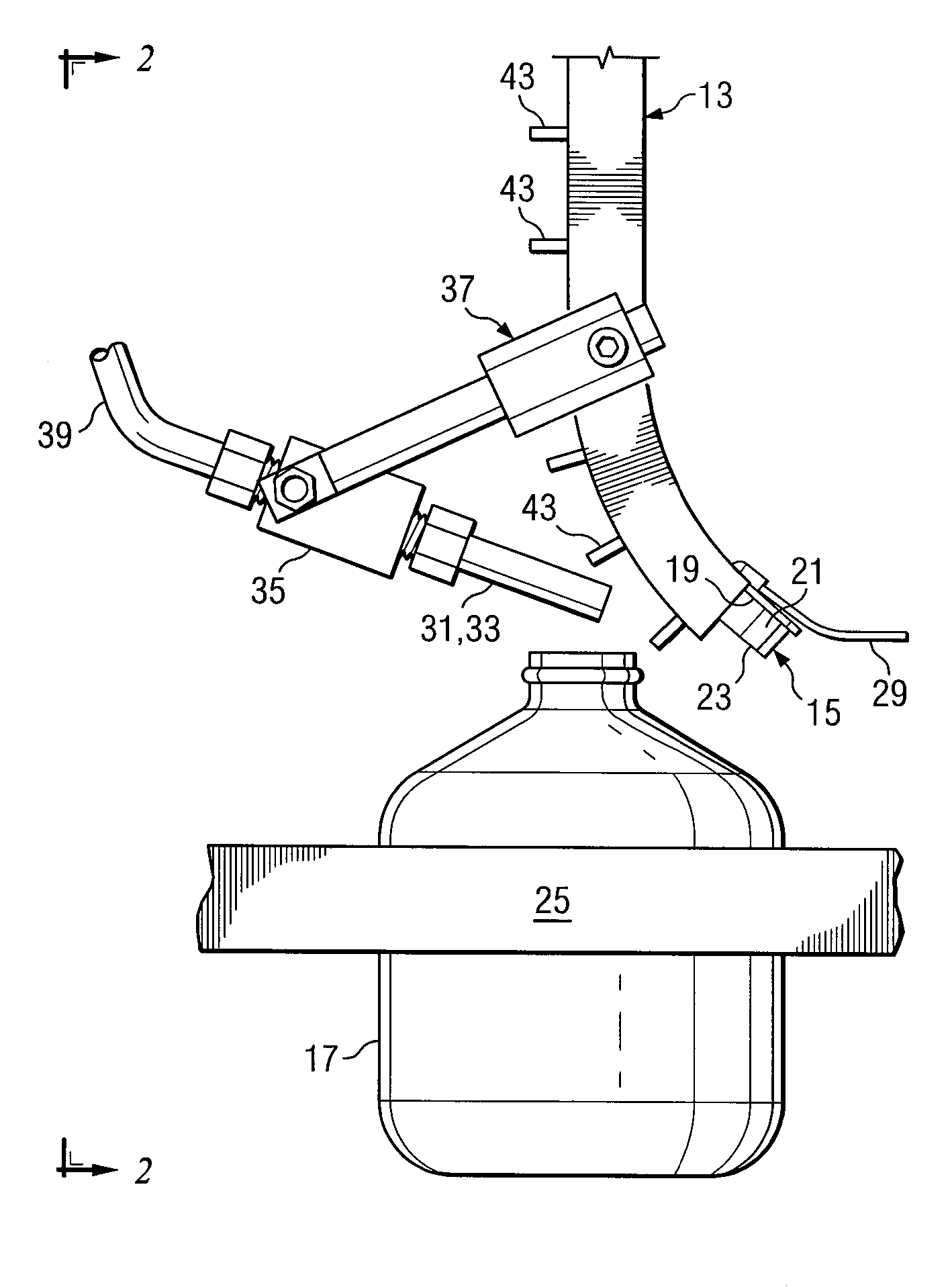
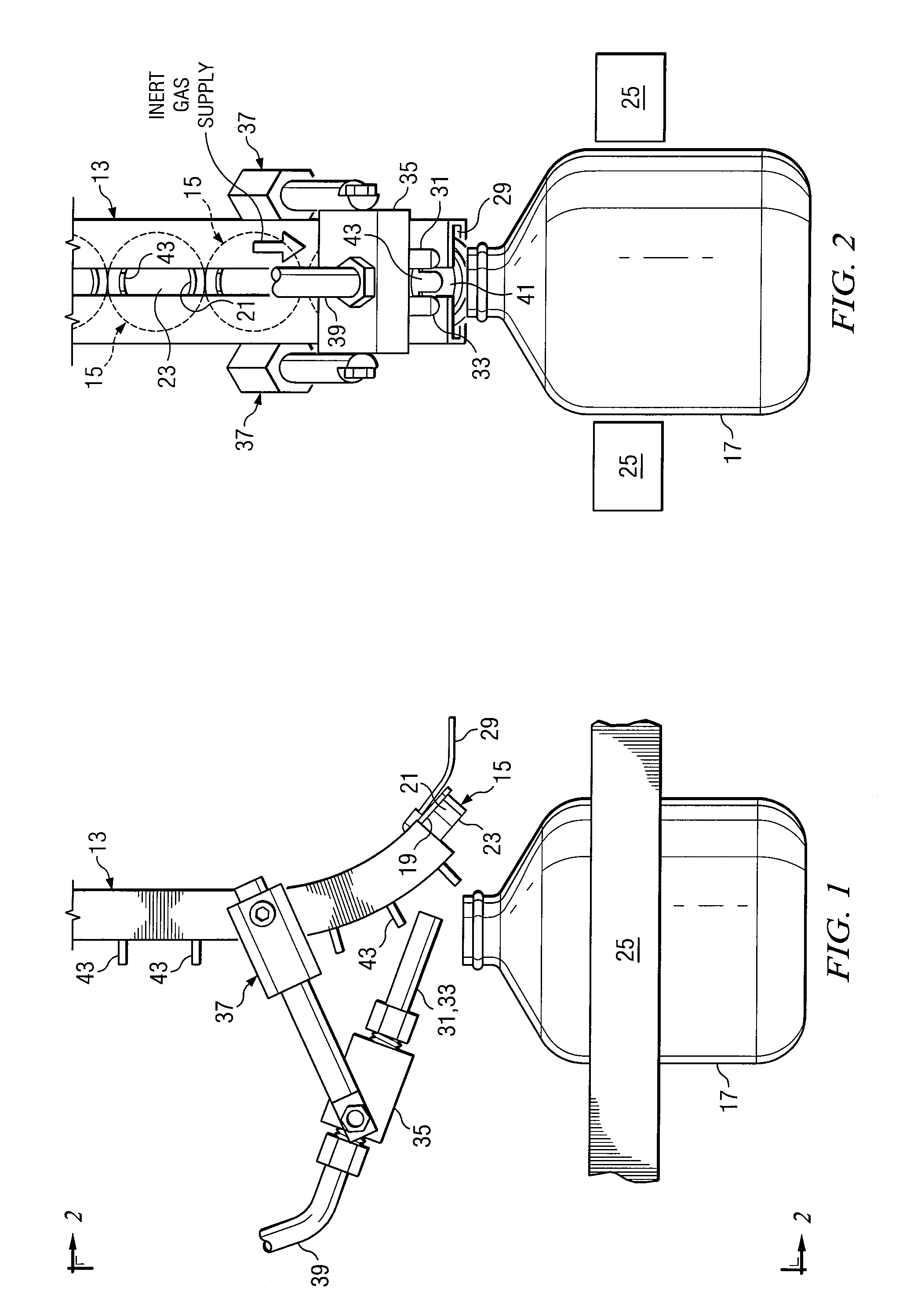
[0023]FIGS. 1 and 2 show a typical apparatus for capping one-gallon plastic milk bottles. The apparatus 11 is shown in schematic with nonessential equipment removed for visibility. Throughout the figures, which are not drawn to scale, equivalent elements are given identical reference numbers. While snap-on caps are shown, it is believed screw-on caps can also make use of the method of the invention for low pressure service, i.e. service in which the pressure in the sealed head space can range from slightly below to slightly above atmospheric pressure when capped, but not at high enough pres...


PUM


Abstract

A process to reduce oxygen in the head space of containers includes introducing an inert gas into the container head space. This may be accomplished during a capping process. The process may further include flushing the container with an inert gas. The flushing step may be performed while the container is empty or prior to being completely filled.

Description

RELATED APPLICATION [0001] This application is a continuation-in-part application claiming the benefit of pending U.S. patent application Ser. No. 11 / 029,326 filed Jan. 5, 2005, entitled Method and Apparatus for Inerting Head Space of a Capped Container and U.S. patent application Ser. No. 11 / 535,150 filed Sep. 26, 2006 entitled Method and Apparatus for Inerting Head Space of a Capped Container.TECHNICAL FIELD OF THE INVENTION [0002] This invention relates to bottling of potable fluids subject to microbial attack. In particular, the invention relates to a method and apparatus for extending the shelf life of such potable fluids stored in non-pressurized containers with snap-on caps by flushing the container with an inert gas. Some embodiments may incorporate a flushing process whereby the container is flushed prior to filling with the potable fluid. Also, certain aspects of the invention may involve at least partially displacing the oxygen in the cap and in the container head space w...

Claims


Application Information

Patent Timeline
Patent Type & Authority Applications(United States)
IPC IPC(8): B65B31/02
CPCB65B31/043B67B3/22B67C3/222B67C3/04B67C3/02B65B7/2807
Inventor RUPPMAN, KURT H. SR.RUPPMAN, KRAIG A.
Owner RUPPMAN KURT H SR
Why Eureka
Try Eureka