Flat-plate heat pipe containing channels

Active Publication Date: 2007-03-15
NATIONAL TSING HUA UNIVERSITY
View PDF11 Cites 57 Cited by
  • Summary
  • Abstract
  • Description
  • Claims
  • Application Information

AI Technical Summary

Benefits of technology

[0011] This invention solves the bumping-up problem for the metal-mesh evaporator in the prior art shown in FIG. 4. While both the permeable dividing layer 205 and the strengthener between the top wall and the

Problems solved by technology

First, as the wick is porous, large friction tends to retard the liquid back flow and lead to dry-out at high heat loading.
The first disadvantage of large friction for liquid flow, however, is not improved in this embodiment.
This leads to attenua

Method used


Image

  • Flat-plate heat pipe containing channels
  • Flat-plate heat pipe containing channels
  • Flat-plate heat pipe containing channels

Examples


Embodiment Construction

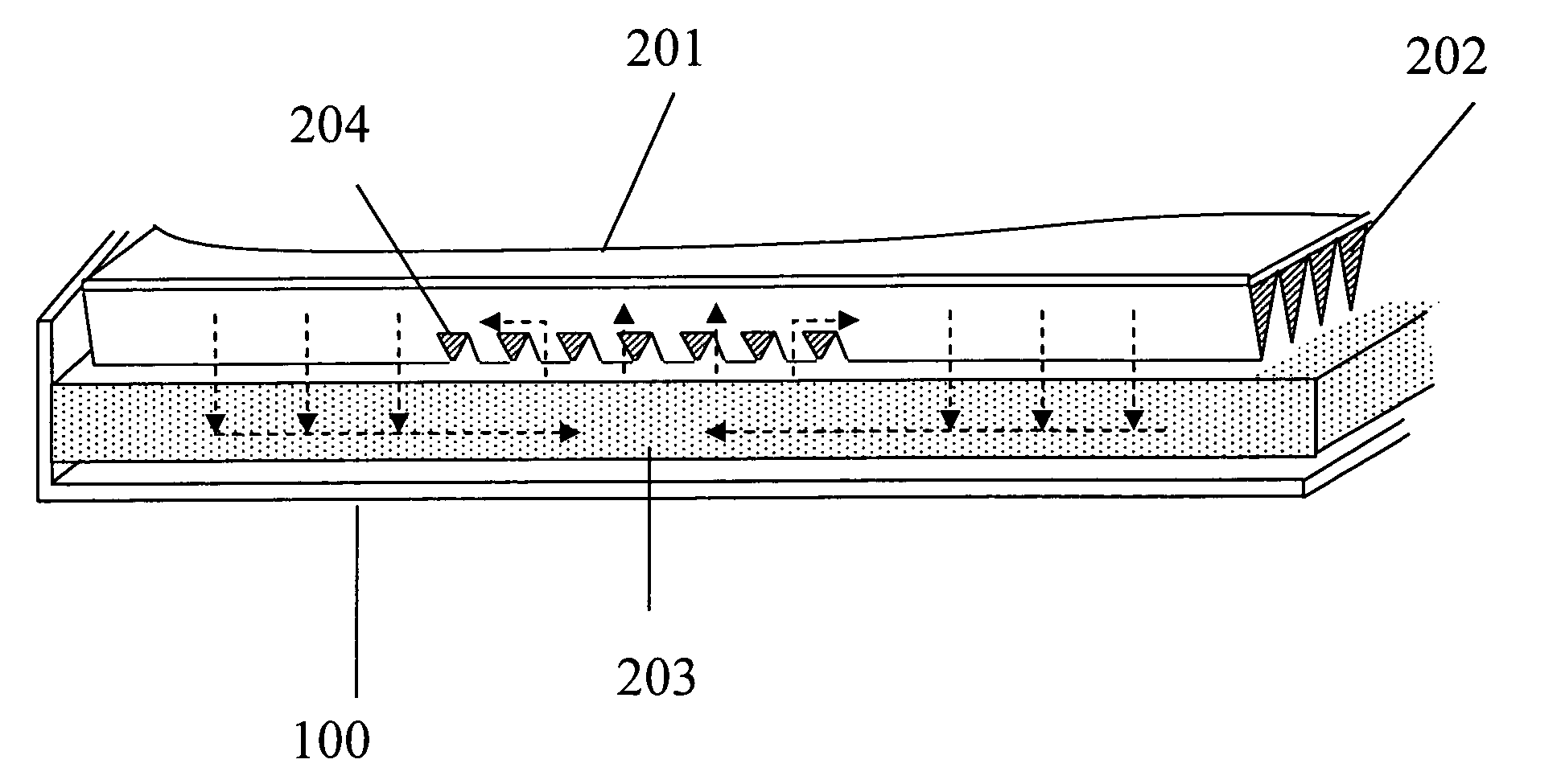
[0020]FIG. 5 discloses a representative embodiment of this invention. The interior of the enclosed metal chamber 100 comprises the upper and lower sections designed for coolant cycling. The permeable dividing layer 205 as well as the open space 300 in FIG. 4 is eliminated so that the parallel grooves 201 contact directly with the wick 203. To allow for efficient vapor distribution, a plurality of cut-off openings 204 are made on the channel walls 202, as shown in FIG. 6. The openings distribute over at least the evaporation region so that the. vapor generated therein can move freely to spread over the space in the upper section. The vapor then condenses on the channel walls 202 with the condensed liquid downward enters the wick 203 directly and is subsequently drawn back to the evaporator. The remaining wall sections between the openings 204 serve as the liquid path to the wick 203, the strengtheners to press down the wick layer 203, and the stiffeners between the top wall and the w...


PUM

PropertyMeasurementUnit
Heataaaaaaaaaa
Distributionaaaaaaaaaa

Abstract

Heat from a heat generating device such as a CPU is dissipated by a heat spreader containing a cycled two-phase vaporizable coolant. The coolant cycles inside a closed metal chamber, which has an upper section and a lower section. The lower section contains a wick layer, a part or parts of which serves as an evaporator. The upper section is composed of a set of channels. The channel walls contain a plurality of cut-off openings over the evaporator region to allow for vapor distribution efficiently. The liquid coolant in the evaporator is vaporized by the heat from the heat generating device. The coolant vapor can prevail in the channels by either directly entering the adjacent channels or indirectly through lateral conduits formed with the wall openings. The vapor condenses on the channel, walls to liberate latent heat which is then dissipated out through the top chamber wall. The condensed coolant is directly collected by the lower-section wick and further flows back to the wick evaporator by capillary action, thereby cycling the coolant.

Description

BACKGROUND OF THE INVENTION [0001] (1) Field of the Invention [0002] This invention relates to a heat pipe, in particular, a grooved flat-plate heat pipe used for heat dissipation for electronic integrated circuit (IC) chips, such as a central processing unit (CPU), or other high-flux heat sources. [0003] (2) Brief Description of Related Art [0004] The latest generation of Pentium IV CPU generates power more than 100 watts (Joule / sec). In order to maintain its normal performance and avoid overheating of the unit, more effective heat dissipating mechanism is needed. A method uses a flat-plate heat pipe, as shown in FIG. 1, for spreading the heat generated by a semiconductor device. An enclosed and vacuumed metal chamber 11, whose inner surface covered with a layer of wick 10, contains a working liquid undergoing a cycling loop. The wick material is commonly sintered metal powder, metal wire mesh, or metal cloth, etc. A part of the wick on the lower surface serves as the evaporator, w...

Claims


Application Information

Patent Timeline
IPC IPC(8): H05K7/20
CPCF28D15/0233F28D15/046F28F2245/02F28F2245/04H01L2924/0002H01L23/427H01L2924/00
Inventor WONG, SHWIN-CHUNG
Owner NATIONAL TSING HUA UNIVERSITY
Why Eureka
Try Eureka