Hydraulic control system for heavy constrution equipment

a technology of hydraulic control system and construction equipment, which is applied in the direction of braking system, coupling, mechanical apparatus, etc., can solve problems such as energy loss

Inactive Publication Date: 2007-03-15
VOLVO CONSTR EQUIP HLDG SWEDEN AB
View PDF5 Cites 1 Cited by
  • Summary
  • Abstract
  • Description
  • Claims
  • Application Information

AI Technical Summary

Benefits of technology

[0015] Accordingly, the present invention has been made to solve the above-mentioned problems occurring in the prior art while advantages achieved by the prior art are maintained intact, and one object of the present invention is to provide a hydraulic control system capable of minimizing the flow rate of a hydraulic fluid being discharged from a main variable displacement hydraulic pump when a switching valve is in a neutral mode, and adjusting the flow rate of the hydraulic fluid being discharged from the main variable displacement hydraulic pump according to the pressure generated in a pressure signal line by a pressure generator when the switching valve is in an operation mode.
[0016] Another object of the present invention is to provide a hydraulic control system capable of minimizing the energy loss that results from drainage of the hydraulic fluid to a tank via a bypass passage when a switching valve is in a neutral mode.

Problems solved by technology

Consequently, since energy corresponding to the drained part is converted into heat, it creates a problem of energy loss.

Method used


Image

  • Hydraulic control system for heavy constrution equipment
  • Hydraulic control system for heavy constrution equipment
  • Hydraulic control system for heavy constrution equipment

Examples


Embodiment Construction

[0030] Hereinafter, a preferred embodiment of the present invention will be described with reference to the accompanying drawings. The matters defined in the description, such as the detailed construction and elements, are nothing but specific details provided to assist those of ordinary skill in the art in a comprehensive understanding of the invention, and thus the present invention is not limited thereto.

[0031] The construction of a hydraulic control system according to the present invention will now be described in detail with reference to preferred embodiments.

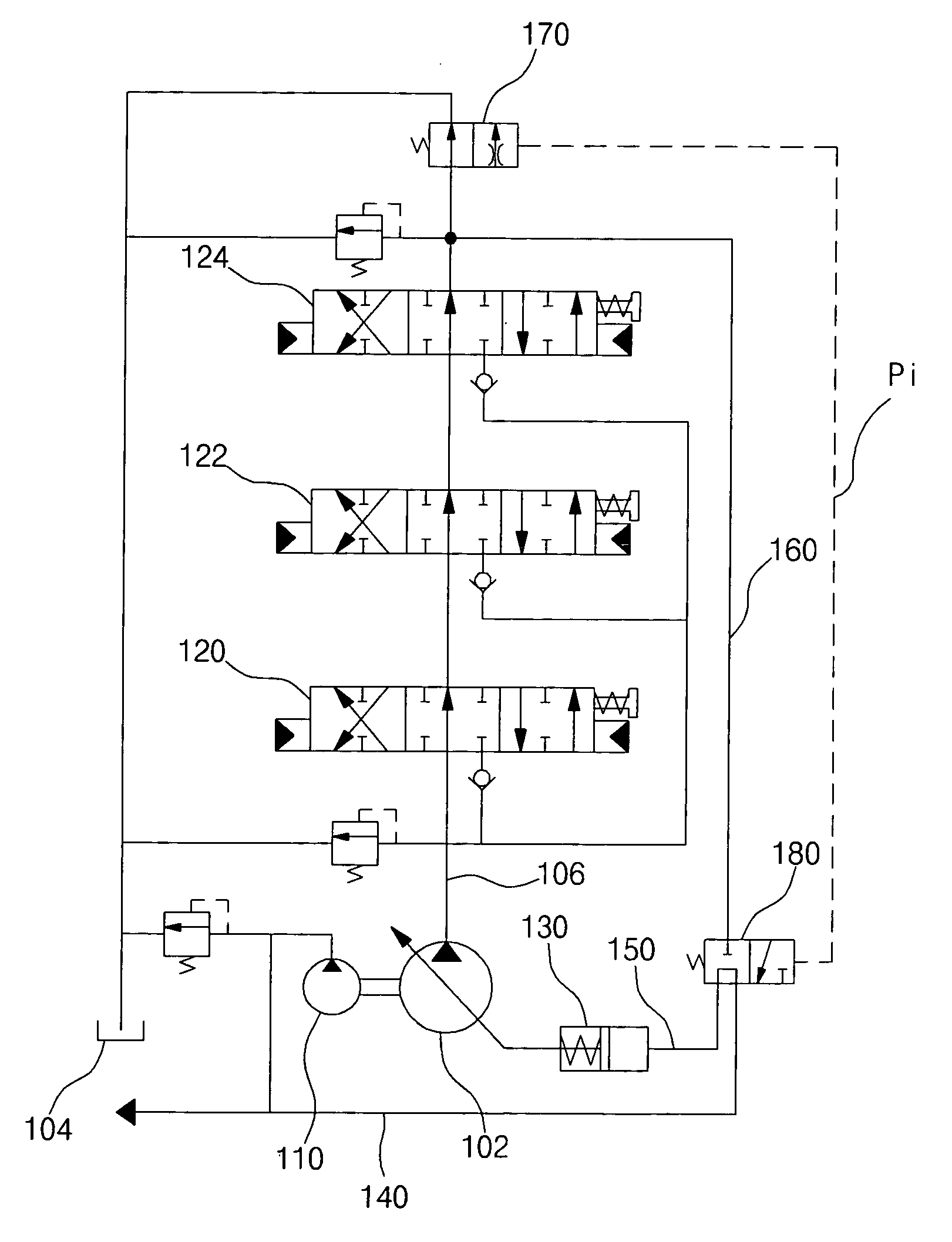
[0032]FIG. 4 is a hydraulic circuit diagram illustrating the construction of a hydraulic control system according to an embodiment of the present invention. FIG. 5 is a pump pressure diagram of FIG. 4. FIGS. 6 and 7 are hydraulic circuit diagrams illustrating the construction of a hydraulic control system according to alternative embodiments of the present invention.

[0033] As shown in FIG. 4, the hydraulic control syst...


PUM


Abstract

A hydraulic control system is disclosed, which can minimize the flow rate of a hydraulic fluid being discharged from a variable displacement hydraulic pump by using pilot pressure constantly produced by a pilot pump when a switching valve is in a neutral position, and can adjust the flow rate of the hydraulic fluid being discharged from the variable displacement hydraulic pump by using pressure produced by a pressure generator positioned at the most downstream side of a bypass passage if a separate input signal is applied to the pressure generator when the switching valve is operated. The hydraulic control system includes a main variable displacement hydraulic pump, a pilot pump, a plurality of actuators, a switching valve interposed between the main pump and the actuators, a load pressure signal passage for guiding a part of the hydraulic fluid to a tank via the first flow control device, and a flow control device for the main pump installed on one side of the main pump to control the flow rate of the hydraulic fluid by adjusting the inclination angle of a swash plate in the main pump.

Description

CROSS-REFERENCE TO RELATED APPLICATION [0001] This application is based on and claims priority from Korean Patent Application No. 10-2005-85993, filed on Sep. 15, 2005, the disclosure of which is incorporated herein in its entirety by reference. BACKGROUND OF THE INVENTION [0002] 1. Field of the Invention [0003] The present invention relates to a hydraulic control system for heavy construction equipment, and more particularly to a hydraulic control system that can minimize the flow rate of a hydraulic fluid being discharged from a variable displacement hydraulic pump by using pilot pressure constantly produced by a pilot pump when a switching valve is in a neutral position, and can adjust the flow rate of the hydraulic fluid being discharged from the variable displacement hydraulic pump by using pressure produced by a pressure generator positioned at the most downstream side of a bypass passage if a separate input signal is applied to the pressure generator when the switching valve ...

Claims


Application Information

Patent Timeline
Patent Type & Authority Applications(United States)
IPC IPC(8): B60T13/16
CPCE02F9/2232E02F9/2296F15B11/055F15B11/165F15B2211/329F15B2211/20553F15B2211/255F15B2211/3116F15B2211/20546F15B9/09F15B21/00
Inventor KOO, BON SEOK
Owner VOLVO CONSTR EQUIP HLDG SWEDEN AB
Why Eureka
Try Eureka