Fluid recovery process and apparatus for xenon and or krypton recovery

a technology fluid recovery, which is applied in the direction of liquefaction, lighting and heating apparatus, separation processes, etc., can solve the problems of increasing xe losses, complex recovery process, and high cost of xenon and krypton recovery

Pending Publication Date: 2022-11-10
AIR PROD & CHEM INC
View PDF5 Cites 0 Cited by
  • Summary
  • Abstract
  • Description
  • Claims
  • Application Information

AI Technical Summary

Benefits of technology

[0005]We have determined that it can be desirable to minimize a flow of a xenon and / or krypton enriched purge stream when such a stream is generated in an air separation column. We have determined that minimizing the flow rate for such a stream can help facilitate further downstream purification to obtain product flows of xenon (Xe) and / or krypton (Kr) at high concentrations sufficient for economical transport to another location for further processing to form product of Xe and / or Kr fluid (e.g. a concentration of at least 20 mole percent (mol %) Xe or at least 20 mol % Kr, etc.) or at sufficiently high concentrations so that a downstream processing facility of the plant can form a product flow of Xe or Kr (e.g. at least 90 mol % Xe, at least 90 mol % Kr, at least 95 mol % Xe, at least 95 mol % Kr, at least 99 mol % Xe, at least 99 mol % Kr, etc.).
[0006]We also determined that low volatility components such as carbon dioxide (CO2) and nitrous oxide (N2O) can concentrate with the Xe and / or Kr and their low solubility limit may determine the minimum flow rate of the Xe and / or Kr enriched purge stream. In the event that the CO2 / N2O content determines the purge flow rate for this stream, we determined that it can be desirable to recycle a fraction of the stream so it is recycled back to a frontend pre-purification unit (PPU) or compression system to subsequently undergo compression and then be passed to the PPU along with compressed feed air so that the recycled portion is passed back through the PPU so further CO2 / N2O components can be removed via the PPU. We determined that the recycling of this portion of the Xe and / or Kr enriched purge stream can allow Kr and Xe to accumulate to a higher concentration in the purge stream that is output for downstream processing to form the Xe and / or Kr product flows. It also allows for minimization of the flow rate of the purge stream. We have determined that such an approach to Xe and / or Kr purge stream processing can allow smaller PPU and downstream processing equipment to be utilized in a plant, which can help reduce capital costs while also permitting a higher purity Xe product flow and / or Kr product flow to be obtained via the downstream processing or to have a more conventional purity of these product streams obtained at a lower processing cost. Embodiments can also help provide improved operational flexibility.
[0007]We have determined that methods and apparatuses that utilize embodiments of our improved Xe and / or Kr recovery scheme permit a smaller flow of Xe and / or Kr enriched stream to be sent to downstream processing while also having a higher Xe concentration and / or a higher Kr concentration than conventional systems without needing the use of one or more cryogenic CO2 / N2O adsorbers or substantially oversizing frontend prepurifier adsorbers. This can result in lower costs for the further downstream processing of the Xe and / or Kr purge stream without penalizing the air separation unit (ASU) cost. We have found that the recycling of a fraction of the Xe and / or Kr enriched purge stream upstream of a frontend PPU to remove additional CO2 and N2O in the recycled stream can provide great process efficiency improvements while also allowing the processing to be more resilient to mal-performance of the frontend adsorbers so that higher CO2 / N2O slippage into the coldbox can be better tolerated. For example, if such a situation is detected as occurring due to adsorbent material or catalyst material becoming deactivated etc., the process can be modified to account for such an occurrence by increasing the fraction of the Xe and / or Kr enriched purge stream recycled upstream for further purification via the PPU.

Problems solved by technology

Because air contains only 1.14 and 0.087 parts per million volume (ppmv) of krypton and xenon, respectively, recovery of these components by the cryogenic separation of air can be technically complex and costly.
Recovery is often further complicated by the presence of light hydrocarbons (e.g. methane) in the air feed of an air separation plant.
A further disadvantage of over-sizing the front-end adsorber that can be solved by embodiments that utilize an embodiment of our Xe and / or Kr recovery scheme is the increasing of Xe losses by co-adsorption of Xe on 13X or other X-zeolite type adsorbents common in air pre-purifiers, e.g. NaMSX, NaLSX, CaX.

Method used


Image

  • Fluid recovery process and apparatus for xenon and or krypton recovery
  • Fluid recovery process and apparatus for xenon and or krypton recovery
  • Fluid recovery process and apparatus for xenon and or krypton recovery

Examples


Embodiment Construction

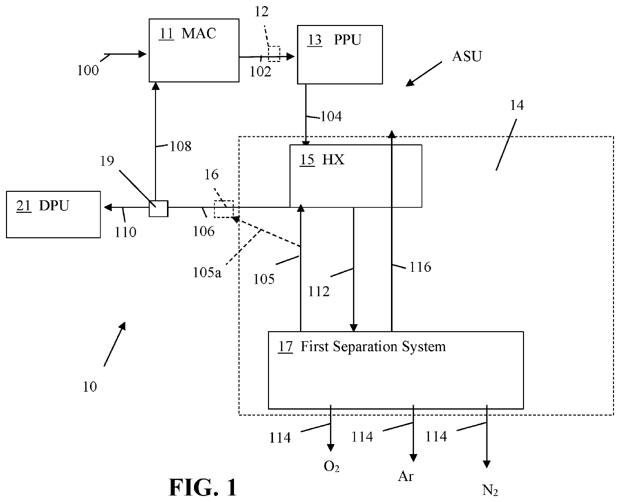
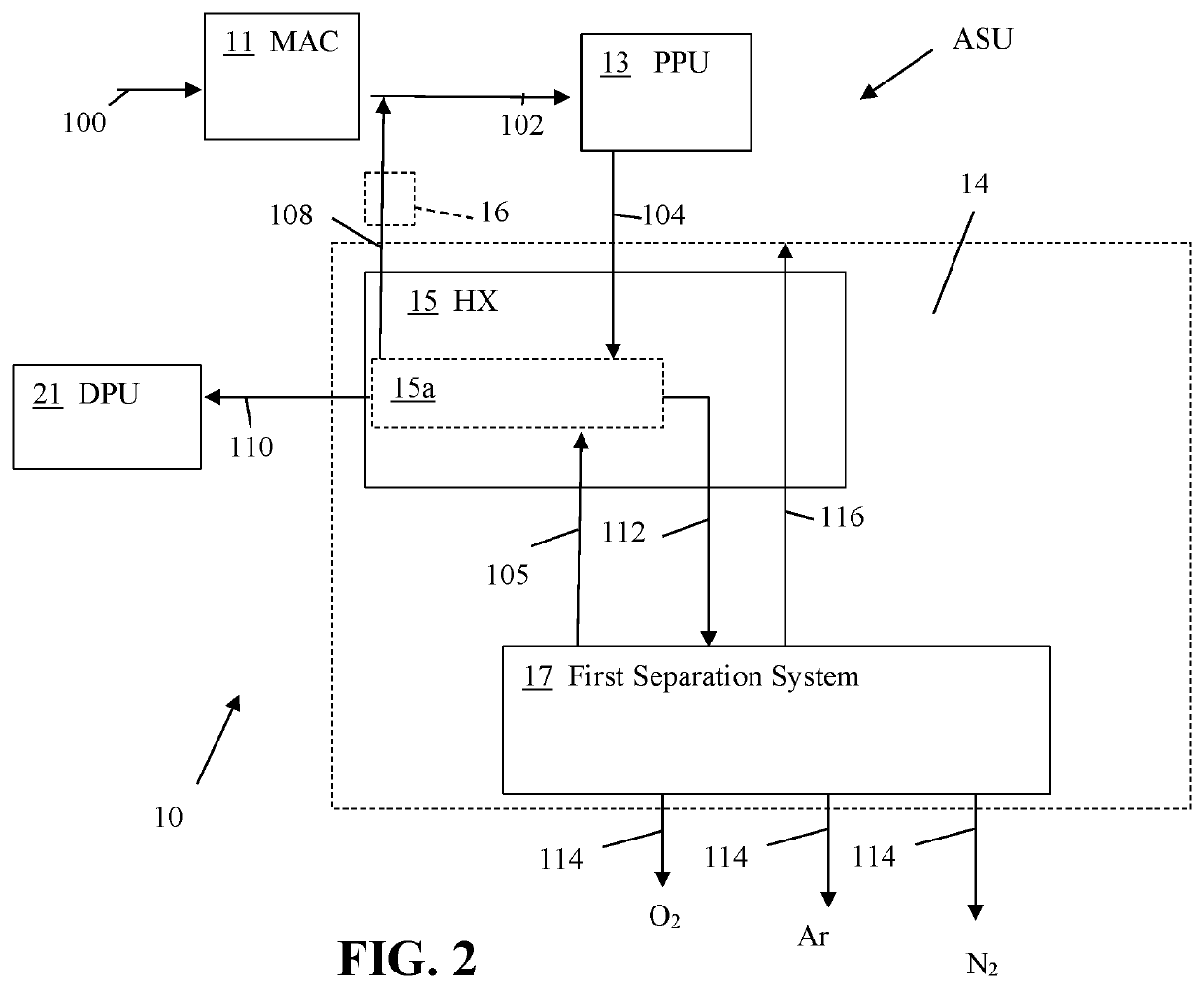
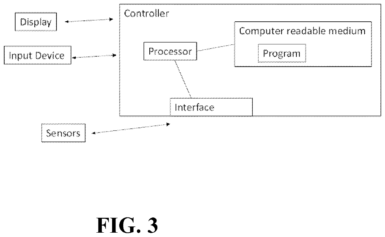
[0036]Referring to FIGS. 1-3, a plant 10 can be configured to utilize an air separation process that can be configured to facilitate recovery of at least one xenon and / or krypton fluid flow 110 in addition to argon, nitrogen, and / or oxygen fluid product flows 114. Embodiments of the plant 10 can utilize a controller, to help monitor and / or control operations of the plant 10. In some embodiments, the plant 10 can be configured as an air separation system or a cryogenic air separation system. The plant 10 can be a standalone facility or be a facility that is incorporated in a larger facility having other plants (e.g. a manufacturing plant for making goods, a mineral refining facility, an electricity generation plant, etc.). The plant 10 can have a single air separation unit (ASU) that can employ an embodiment of the air separation process or can utilize multiple different ASUs. One or more of the ASUs in an embodiment of the plant having multiple ASUs can utilize an embodiment of the ...


PUM


Abstract

A process for recovering at least one fluid (e.g. xenon gas and / or krypton gas, etc.) from a feed gas can include utilization of a compression system, primary heat exchanger unit, a pre-purification unit (PPU), and other units to separate and recover at least one desired fluid. In some embodiments, fluid flows output from a first heat exchanger or separation system of the plant can be split so that a portion of a stream is output for downstream processing to purify xenon (Xe) and / or krypton (Kr) product flow(s) while another portion of the stream is recycled to a compression system or the PPU to undergo further purification and heat exchange so that the product output for downstream processing has a higher concentration of Xe or Kr. Some embodiments can be configured to provide an improved recovery of Xe and / or Kr as well as an improvement in operational efficiency.

Description

FIELD OF THE INVENTION[0001]The present innovation relates to processes utilized to recover fluids (e.g. xenon, krypton, oxygen, argon and / or nitrogen) from air, gas separation plants configured to recover xenon and / or krypton in addition to nitrogen, argon and / or oxygen from at least one feed gas, air separation plants, air separation systems, systems utilizing multiple columns to recover xenon and / or krypton fluid in addition to nitrogen, argon, and / or oxygen fluids, and methods of making and using the same.BACKGROUND OF THE INVENTION[0002]Air separation processes can be configured to recover rare gases such as xenon (Xe) or krypton (Kr) as well as neon (Ne), helium (He), and / or argon (Ar). U.S. Pat. Nos. 4,568,528, 5,309,719, 6,164,089, 6,658,894, 6,735,980, 6,843,973, 6,848,269, 7,285,154, and 8,795,411 disclose examples of such systems.[0003]Neon, argon, krypton, and xenon historically have often been recovered as secondary products in the cryogenic separation of air into oxyge...

Claims


Application Information

Patent Timeline
Patent Type & Authority Applications(United States)
IPC IPC(8): F25J3/04
CPCF25J3/04745F25J3/048F25J3/04169F25J2205/60F25J2210/06F25J2210/42F25J2210/50F25J2210/58F25J2210/80F25J2215/34F25J2215/36B01D53/0446B01D53/0438C01B13/027C01B21/0466C01B23/0068B01D2253/108B01D2257/402B01D2257/504B01D2256/10B01D2256/12B01D2256/18B01D2259/40086C01B2210/0034C01B2210/0035C01B2210/0037F25J3/04969F25J2210/04F25J3/04957F25J3/0486F25J2245/50Y02C20/40F25J3/04757F25J3/04793F25J3/04963F25J2200/32F25J2200/34F25J2200/90
Inventor O'CONNOR, DECLAN PATRICKLAU, GARRET C.
Owner AIR PROD & CHEM INC
Why Eureka
Try Eureka