
Control method of cooling system for vehicle

a technology for cooling systems and vehicles, applied in the direction of machines/engines, process and machine control, instruments, etc., can solve the problems of deterioration of engine performance, increased fuel consumption, and deterioration of lubrication performance, so as to improve fuel efficiency of vehicles, improve cooling performance, and effectively adjust the temperature of coolan

Active Publication Date: 2021-01-12
HYUNDAI MOTOR CO LTD +1
View PDF37 Cites 1 Cited by
  • Summary
  • Abstract
  • Description
  • Claims
  • Application Information

AI Technical Summary

Benefits of technology

The present invention provides a method for controlling a vehicle cooling system to improve cooling efficiency and controllability by adjusting the flow of coolant through a control valve. This allows for better cooling performance and reduces fuel consumption by controlling the temperature of the coolant. The method also minimizes the flow of coolant to the heater, improving overall cooling controllability and customer satisfaction. Additionally, the method optimizes the flow rate of coolant cooled through the radiator and improves engine cooling efficiency.

Problems solved by technology

When a coolant temperature of the engine is excessively high, knocking occurs, and thus ignition timing needs to be adjusted to suppress occurrence of knocking, thereby causing deterioration of engine performance.
When a lubricant temperature is too high, viscosity becomes low, thereby causing deterioration of lubrication performance.
Further, when a coolant temperature of the engine is excessively low, oil viscosity is increased and thus frictional force is increased, fuel consumption is increased, a temperature of exhaust gas is slowly increased.
Accordingly, the time to activate a catalyst is increased and quality of exhaust gas is deteriorated.
In addition, time taken for normalizing the heater is increased, thereby causing inconvenience to a driver or an occupant within the vehicle.
In particular, since viscosity of engine oil is increased when the engine is started in a cold condition such as a winter season, engine output and efficiency are deteriorated, thereby causing deterioration of fuel efficiency.
Further, since incomplete combustion of fuel occurs when a temperature of the combustion chamber is low, exhaust gas may be excessively discharged.

Method used


Image

  • Control method of cooling system for vehicle
  • Control method of cooling system for vehicle
  • Control method of cooling system for vehicle

Examples


Embodiment Construction

[0030]It is understood that the term “vehicle” or “vehicular” or other similar term as used herein is inclusive of motor vehicles in general such as passenger automobiles including sports utility vehicles (SUV), buses, trucks, various commercial vehicles, watercraft including a variety of boats and ships, aircraft, and the like, and includes hybrid vehicles, electric vehicles, combustion, plug-in hybrid electric vehicles, hydrogen-powered vehicles and other alternative fuel vehicles (e.g. fuels derived from resources other than petroleum).

[0031]Although exemplary embodiment is described as using a plurality of units to perform the exemplary process, it is understood that the exemplary processes may also be performed by one or plurality of modules. Additionally, it is understood that the term controller / control unit refers to a hardware device that includes a memory and a processor. The memory is configured to store the modules and the processor is specifically configured to execute ...


PUM


Abstract

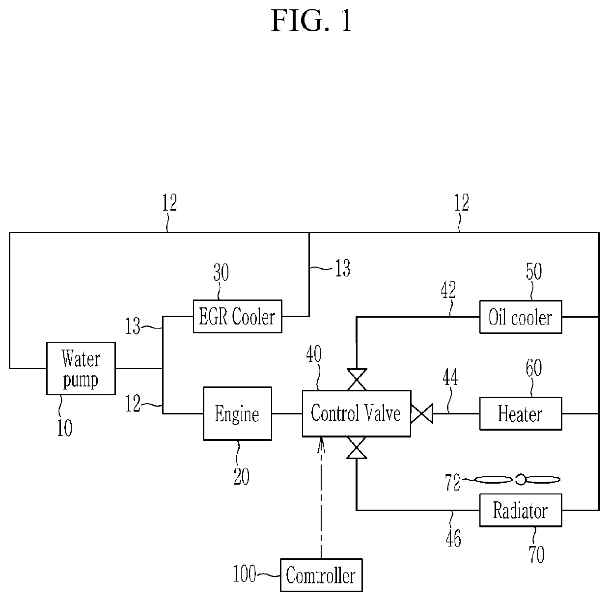
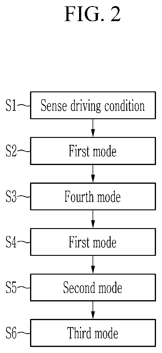
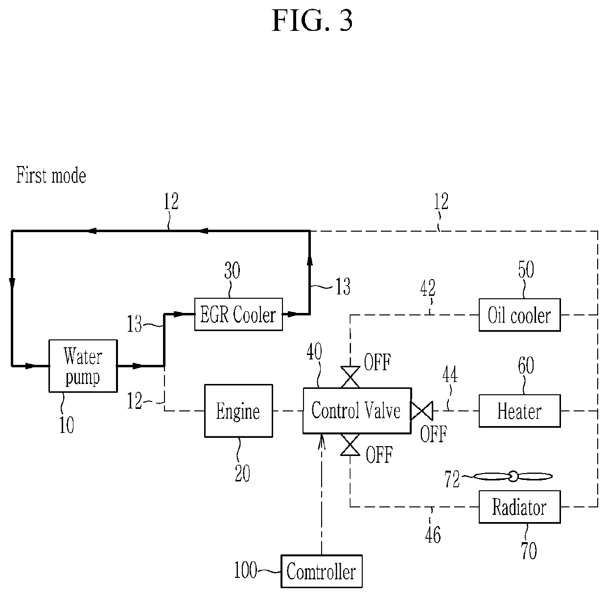
A method for controlling a cooling system for a vehicle is provided. The system includes an engine, an EGR cooler, an oil cooler, a heater, a radiator, and a controller. The engine, the EGR cooler, the oil cooler, the heater, and the radiator are respectively connected through a coolant line and coolant circulates through the engine, the EGR cooler, the oil cooler, the heater, and the radiator by operation of a water pump. The controller receives the coolant from the engine and operates a control valve connected with the oil cooler, the heater, and the radiator. The method includes: sensing driving conditions and operating the control valve when a cooling mode is required to decrease the temperature within the vehicle based on the sensed driving conditions. The control valve is operated based on modes controlled depending on a coolant temperature, and among the plurality of modes, one is iteratively performed.

Description

CROSS-REFERENCE TO RELATED APPLICATION[0001]This application claims priority to and the benefit of Korean Patent Application No. 10-2018-0089819 filed on Aug. 1, 2018, the entire contents of which are incorporated herein by reference.BACKGROUND(a) Field of the Invention[0002]The present invention relates to a method for controlling a cooling system for a vehicle, and more particularly, to a method for controlling a cooling system for a vehicle to improve fuel efficiency of the vehicle by adjusting coolant flow in a cooling mode that cools the interior of the vehicle.(b) Description of the Related Art[0003]In general, an engine exhausts heat energy while generating torque from combustion of fuel, and a coolant absorbs the heat energy while circulating through the engine, a heater, and a radiator, and emits the absorbed heat energy to the outside. When a coolant temperature of the engine is excessively high, knocking occurs, and thus ignition timing needs to be adjusted to suppress oc...

Claims


Application Information

Patent Timeline
Patent Type & Authority Patents(United States)
IPC IPC(8): G05D23/00F01P7/16F02M26/32F02M26/30F02M26/24F02M26/28F02M26/33F01P7/14
CPCF01P7/167F02M26/24F02M26/28F02M26/30F02M26/32F02M26/33F01P2007/146F01P3/20F01P7/14F01P5/10F01P3/18F01P5/02F01P7/08F01M5/002F02M26/23B60H1/00271B60H1/03B60H2001/00307F01P2060/18F01P2060/04F01P7/165B60H1/00885F01P2025/08
Inventor KIM, HAN SANG
Owner HYUNDAI MOTOR CO LTD
Learn More