Dynamoelectric stator

a dynamoelectric stator and stator body technology, applied in the direction of dynamo-electric components, synchronous machines, windings, etc., can solve the problems of reducing the reliability affecting the work efficiency affecting the performance of the dynamoelectric machine, so as to improve the vibration resistance of the lead portion, increase the work or cost, and reduce the effect of area

Inactive Publication Date: 2007-03-15
MITSUBISHI ELECTRIC CORP
View PDF3 Cites 2 Cited by
  • Summary
  • Abstract
  • Description
  • Claims
  • Application Information

AI Technical Summary

Benefits of technology

[0011] According to the present invention, because the unjoined phase winding lead portions are fastened to each other using the fastening member, it is not necessary to form restricting recess portions for restricting the position of the lead portions on the first coil end, enabling vibration resistance of the lead portions to be improved without increasing work or cost.
[0012] Because the lead portions are led around circumferentially along the apex portion of the coil end group so as to be separated from the apex portion, clearance is ensured between the lead portions and the first coil end group. Thus, reductions in area of the lead portions and the first coil end group exposed to cooling airflows are suppressed, suppressing excessive stator winding temperature increases.
[0013] In addition, because the lead portions are led around along the apex portion of the first coil end group, the lead portions can be disposed without increasing radial dimensions of the stator which constitutes a factor in increasing body size of dynamoelectric machines.

Problems solved by technology

In conventional dynamoelectric stators according to Patent Literature 1, because the bond strength between the lead portions and the coil end group is affected by layout of the lead portions relative to the coil end group, it has been difficult to achieve stable bond strength between the two.
Thus, there is a risk that the lead portions may be dislodged from the coil end group due to vibrations from an engine when a vehicle mounted with a dynamoelectric machine is driven.
Thus, because lead portions that have dislodged from the coil end group shake and move around, giving rise to wire breakages in the lead portions, and also rub against the coil end group, giving rise to damage to the coil end group, one problem has been that reliability of the dynamoelectric machine is reduced.
In conventional dynamoelectric stators according to Patent Literature 2, because it is necessary to dispose the restricting recess portions so as to correspond to each of the lead portions, making the configuration of the coil end complicated, one problem has been that forming the coil end is troublesome and expensive.
Because the lead portions are housed inside the restricting recess portions and additionally embedded in the adhesive, area of the lead portions and the coil end group exposed to cooling airflows is reduced, and there is a risk that this may have adverse thermal effects.

Method used


Image

  • Dynamoelectric stator
  • Dynamoelectric stator
  • Dynamoelectric stator

Examples


Embodiment Construction

[0019] A preferred embodiment of the present invention will now be explained with reference to the drawings.

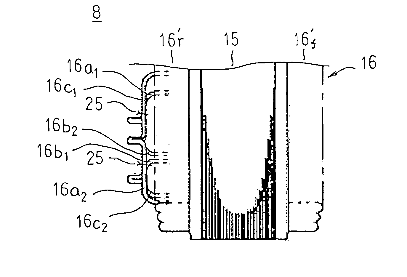
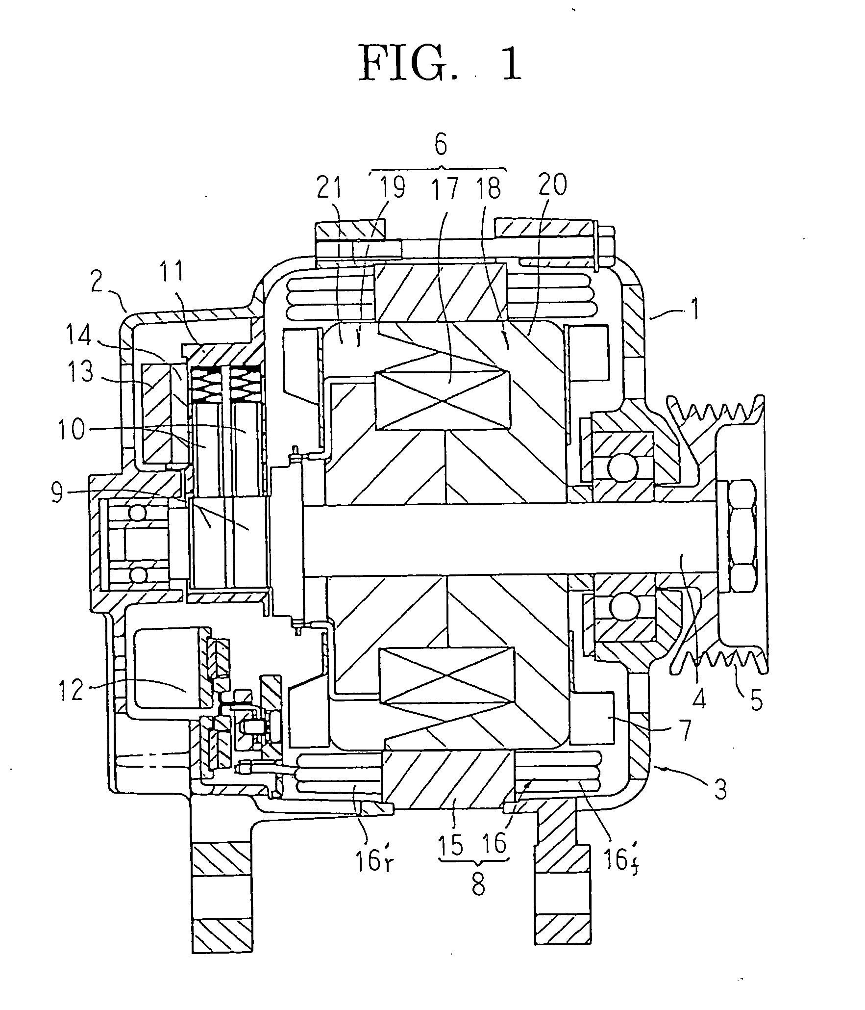
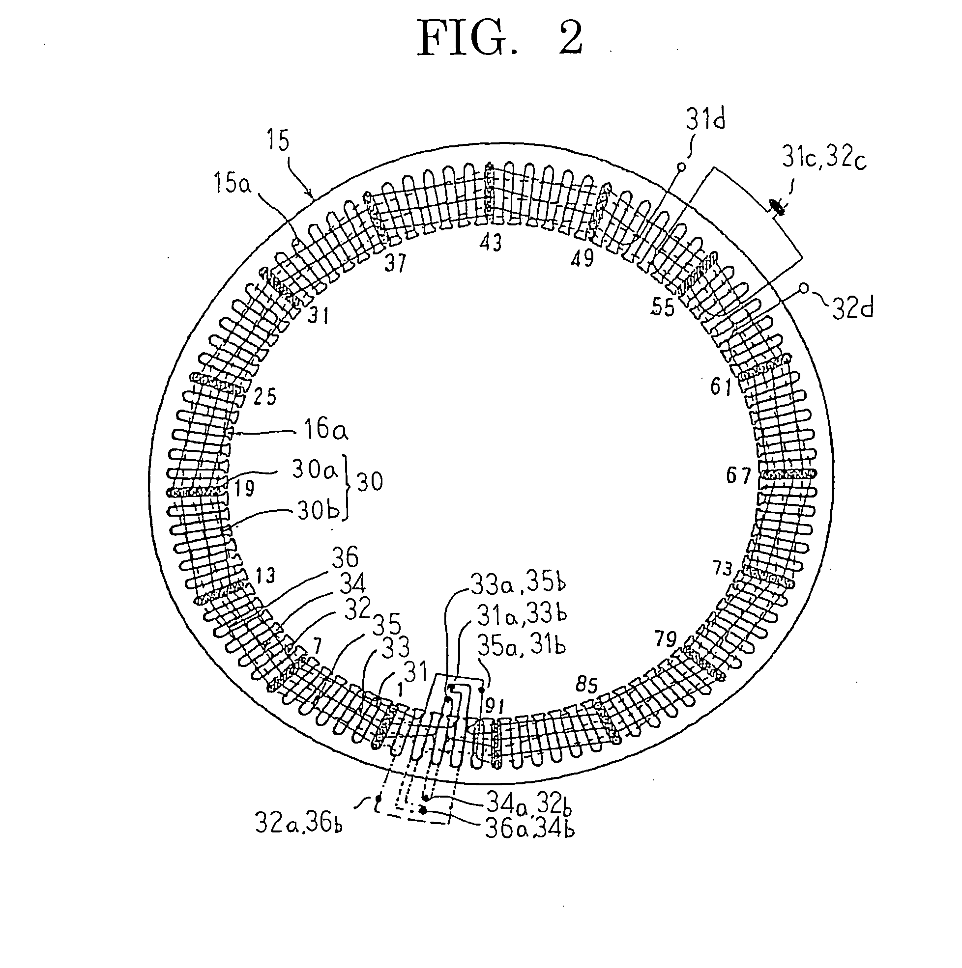
[0020]FIG. 1 is a longitudinal section showing a dynamoelectric machine mounted with a stator according to a preferred embodiment of the present invention, FIG. 2 is a rear-end end elevation of a stator core explaining a configuration of a stator winding in the stator according to the preferred embodiment of the present invention, FIG. 3 is a circuit diagram for the dynamoelectric machine mounted with the stator according to the preferred embodiment of the present invention, FIG. 4 is a side elevation showing part of the stator according to the preferred embodiment of the present invention, and FIG. 5 is a view from a rear end of part of the stator according to the preferred embodiment of the present invention.

[0021] In FIG. 1, a dynamoelectric machine includes: a case 3 constituted by a front bracket 1 and a rear bracket 2 made of aluminum that are each generally bowl-shape...


PUM


Abstract

First and second lead portions of an a-phase winding, a b-phase winding and a c-phase winding are each led out from a rear-end coil end group, and subsequently led around circumferentially along an apex portion of the rear-end coil end group so as to be separated from the apex portion. In addition, the first lead portions and the second lead portions are bent axially so as to contact each other closely and are joined together. The first lead portions are fastened by ties in a vicinity of the bent portion extending to the joined portion of the first lead portion, and the second lead portions are fastened by ties in a vicinity of a portion at which the first lead portion is led out from the rear-end coil end group.

Description

BACKGROUND OF THE INVENTION [0001] 1. Field of the Invention [0002] The present invention relates to a dynamoelectric stator for an automotive alternator, etc., and particularly relates to a fixing construction for a lead portion led out from a coil end group of a stator winding. [0003] 2. Description of the Related Art [0004] In conventional dynamoelectric stators, lead portions constituting a portion of a plurality of phase windings are laid circumferentially along surface of a coil end group and fixed to the coil end group using an adhesive (See Patent Literature 1, for example). In addition, in order to increase bond strength between the lead portions and the coil end group, restricting recess portions corresponding to a lead portion shape may be disposed on apex portions of the coil end group and the lead portions positioned inside the restricting recess portions and fixed using an adhesive (See Patent Literature 2, for example). [0005] Patent Literature 1: Japanese Patent Laid...

Claims


Application Information

Patent Timeline
Patent Type & Authority Applications(United States)
IPC IPC(8): H02K11/00H02K3/00
CPCH02K3/12H02K3/50H02K3/28
Inventor NISHITANI, SHOICHIROMIYAJI, WAKAKI
Owner MITSUBISHI ELECTRIC CORP
Why Eureka
Try Eureka