Method of locating pipelines using RFID technology

Active Publication Date: 2007-03-15
CORBETT JR BRADFORD G
View PDF3 Cites 37 Cited by
  • Summary
  • Abstract
  • Description
  • Claims
  • Application Information

AI Technical Summary

Benefits of technology

[0020] In another embodiment of the present invention, a method of locating an underground pipe is shown in which a wireless RFID is associated with the underground pipeline or pipeline component. The RFID can be associated with the pipe in several different ways. The RFID may be directly attached to an exterior or interior surface of the pipe, embedded within the pipe walls during construction of the pipe, or alternatively the RFID may be placed inside a sealing gasket that is then installed inside the pipe. The RFID

Problems solved by technology

This solution is unsatisfactory because it is both slow and expensive, due to the high reliance on manual labor, and because mistakes occur in identifying and sorting the items.
For example, identification schemes which relay upon reading bar codes or other optical indicia are not well suited for use in the sorting of flat goods rather than contoured items.
However, in the case of gasket manufacture, the items in question range in size from very small to large and are typically processed in a variety of orientations which are problematical for line of sight reading devices.
There are other barriers and obstacles to the accurate machine identification and automated counting and sorting of sealing gaskets of the type under consideration.
These type demands have frustrated efforts to adapt bar codes and other optical indicia to sealing gasket technol

Method used


Image

  • Method of locating pipelines using RFID technology
  • Method of locating pipelines using RFID technology
  • Method of locating pipelines using RFID technology

Examples


Example

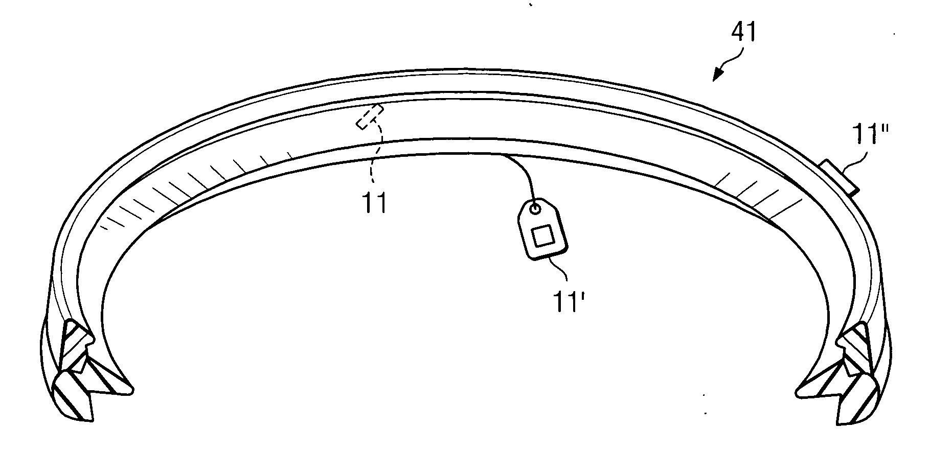
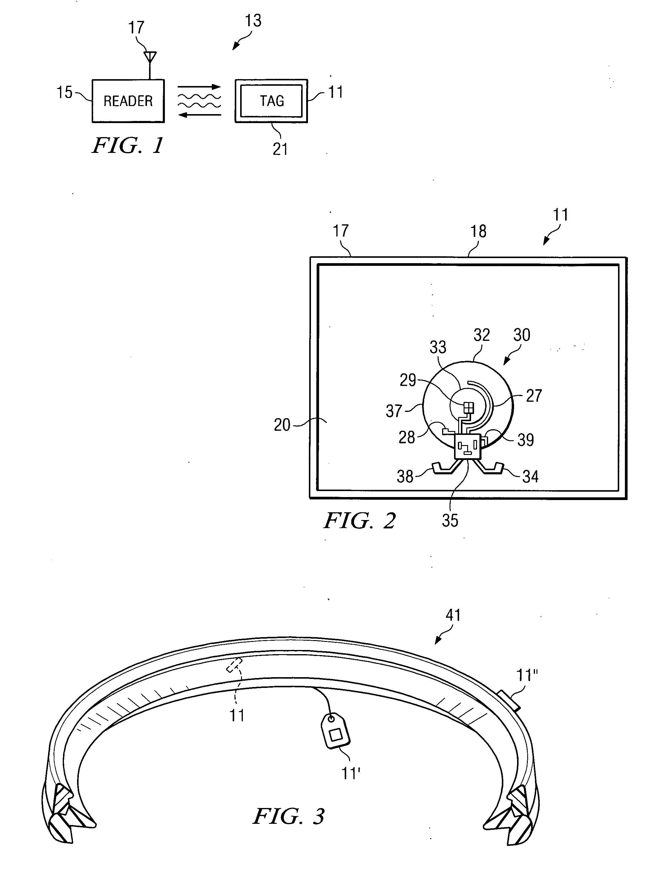
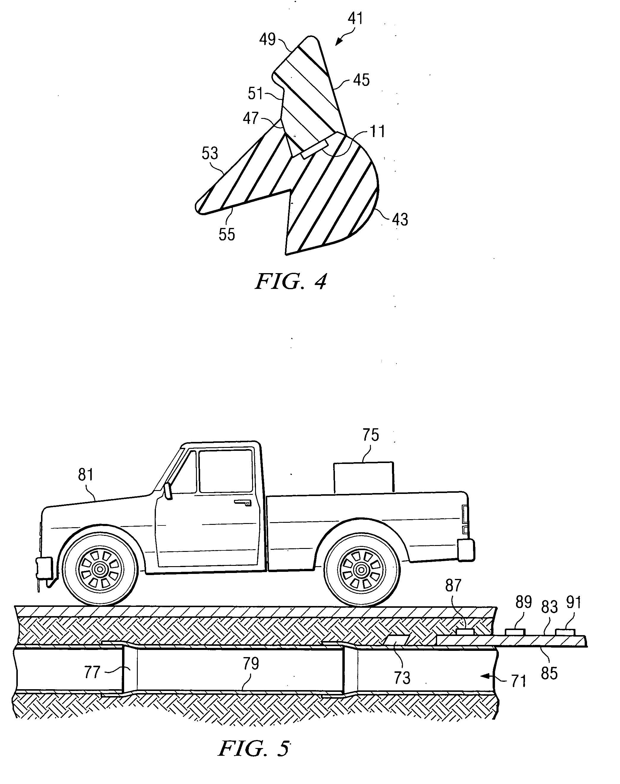
[0027] The system of the invention uses wireless radio frequency identification devices (RFID's) to mark, track and identify items of interest, such as the sealing gaskets used in fluid conveyance systems including municipal water and sewer lines. The system also allows a user to quickly and easily determine the location of a hidden pipeline, such as an underground pipeline.

[0028] RFID technology will first be described in general terms before turning to the more specific end applications of the invention. Whereas RFID's were, in the past, cost prohibitive, such devices can now be purchased commercially for on the order of 20 to 30 cents apiece, making them suitable for the purposes of the present invention. RFID tags are now well-known and typically include an integrated circuit (IC) that is operatively coupled to an antenna (the tag antenna). The tag may also have a battery, or it may have no battery and may instead obtain energy from an external reader. RFID tags without batteri...


PUM


Abstract

A system is shown for locating hidden pipelines, particularly underground pipe used in a plastic pipeline such as for municipal water and sewer applications. An RFID tag is associated with the pipeline prior to installation of the pipeline into the ground. This can be done by associating the RFID tag with a sealing gasket which is subsequently installed at a sealing joint location of the pipeline. The tag can also be associated with the pipeline itself by installing the tag on a section of pipe. The location of the subsequently buried pipeline can be determined by interrogating the RFID tag with a suitable reader, the reader being located at an above ground location.

Description

CROSS REFERENCE TO RELATED APPLICATIONS [0001] The present application is a continuation-in-part of earlier filed application Ser. No. 11 / 033,210, filed Jan. 11, 2005, by the same inventor.BACKGROUND OF THE INVENTION [0002] 1. Field of the Invention [0003] The present invention relates to radio frequency identification (RFID) systems for identification, marking and tracking of selected items, and more specifically to one embodiment of such a system for locating pipelines and components thereof of the type used in water, sewage and other types of fluid conveyance systems. [0004] 2. Description of the Prior Art [0005] There exists a need in a number of different industries for improvements in the way that items are identified, marked and tracked. This is especially true where a large number of items must be separated, identified, counted and sorted. One example is the manufacture of sealing gaskets for use in water, sewage and fluid conveyance systems generally. Present day means for ...

Claims


Application Information

Patent Timeline
IPC IPC(8): H04Q5/22
CPCF16L1/11G06K2017/0045G01V15/00
Inventor CORBETT, BRADFORD G. JR.
Owner CORBETT JR BRADFORD G
Why Eureka
Try Eureka