
Multiple-view directional display

a directional display and multi-view technology, applied in the field of multi-view directional display, can solve the problems of occupying a lot of space, increasing the cost, and requiring a separate display screen for each player, and achieve the effect of reducing the thickness

Active Publication Date: 2007-03-15
SHARP KK
View PDF23 Cites 80 Cited by
  • Summary
  • Abstract
  • Description
  • Claims
  • Application Information

AI Technical Summary

Benefits of technology

[0037] Putting the parallax optic within the image display element puts the parallax optic closer to the image display layer, thereby reducing the separation s of equation (1) and increasing the angular separation between two viewing windows produced by the display device. It is not necessary to reduce the thickness of one of the substrates of the image display element, so that the structural strength of the image display element is not affected.
[0039] The parallax optic may be disposed between the first substrate and the second substrate. This is a convenient way of placing the parallax optic close to the image display layer. Alternatively, the parallax optic may be disposed within one of the first substrates or the second substrate. This is another method of enabling the parallax optic to be placed closer to the image display layer without reducing the thickness of the substrates of the image display element.

Problems solved by technology

These conflicting needs could be satisfied by providing two separate display devices, but this would take up extra space and would increase the cost.
Furthermore, if two separate displays were used in this example it would be possible for the driver to see the passenger's display if the driver moved his or her head, which would be distracting for the driver.
However, providing a separate display screen for each player takes up a lot of space and is costly, and is not practical for portable games.
However, the two images displayed on an autostereoscopic display are the left-eye and right-eye images of a stereoscopic image pair, and so are not independent from one another.
Holographic methods of image splitting are known, but in practice these methods suffer from viewing angle problems, pseudoscopic zones and a lack of easy control of the images.
One problem with many existing multiple view directional displays is that the angular separation between the two images is too low.
This results in a threefold increase in pixel width and therefore roughly three times increase in viewing angle.
This has the disadvantage that the pitch of the parallax barrier pitch must increase as the pixel pitch increases which, in turn, increases the visibility of the parallax barrier to an observer.
The manufacture and driving of such a non-standard panel may not be cost effective.
In addition there may be applications in which the increase in viewing angle needs to be greater than three times the standard configuration and in these cases simply rotating the pixels will not be sufficient.
In general, however, the pixel pitch is typically defined by the required resolution specification of the display device and therefore cannot be changed.
It is not always practical or cost effective significantly to change the refractive index of the substrates, which are normally made of glass.
However, this has been difficult as will be explained with respect to FIG. 5, which is a schematic block view of the display device 1 of FIG. 1 with an LCD as the SLM 4.
Reducing the thickness of the CF substrate will reduce the distance between the LCD pixels and the parallax optic, but will make the substrate correspondingly weaker.
A realistic minimum for LC substrate thickness is about 0.5 mm, but the pixel-to-parallax optic separation would still be too large for many applications if a parallax optic were adhered to a substrate of this thickness.
This reduces the separation between the parallax barrier and the pixel plane by the thickness of the polariser, but this results in only a limited increase in the angular separation between the viewing windows of a multiple-view directional display device.

Method used


Image

  • Multiple-view directional display
  • Multiple-view directional display
  • Multiple-view directional display

Examples


Embodiment Construction

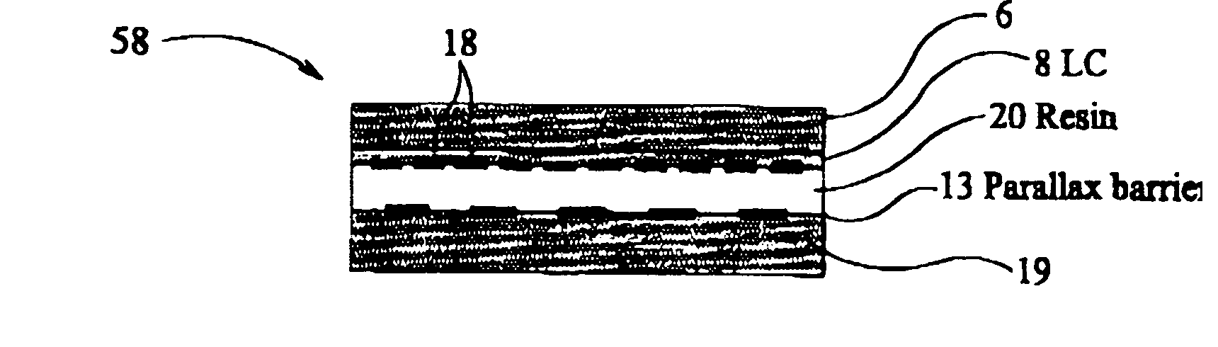
[0117]FIG. 6(b) is a schematic plan view of a multiple-view directional display according to a first embodiment of the present invention. The display device 58 comprises a first transparent substrate 6 and a second transparent substrate 7, with an image display layer 8 disposed between the first substrate 6 and the second substrate 7. An array of colour filters 18 is provided on the second substrate 7, and the second substrate will therefore be referred to as a colour filter substrate.

[0118] The first substrate 6 is provided with pixel electrodes (not shown) for defining an array of pixels in the image display layer 8, and is also provided with switching elements (not shown) such as thin film transistors (TFTs) for selectively addressing the pixel electrodes. The substrate 6 will be referred to as a ‘TFT substrate’.

[0119] The image display layer 8 is, in this example, a liquid crystal layer 8. The invention is not limited to this, however, and any transmissive image display layer ...


PUM


Abstract

A multiple-view directional display is provided having an image display element and a parallax optic (13). The display element (8) comprises substrates (6, 19) between which the display layer (8) is sandwiched and the parallax optic (13) is disposed within the image display element.

Description

FIELD OF THE INVENTION [0001] The present invention relates to a multiple-view directional display, which displays two or more images such that each image is visible from a different direction. Thus, two observers who view the display from different directions will see different images to one another. Such a display may be used as, for example, an autostereoscopic display device or a dual view display device. The invention also relates to a parallax barrier substrate, and to a method of manufacturing a multiple-view directional display. BACKGROUND OF THE INVENTION [0002] For many years conventional display devices have been designed to be viewed by multiple users simultaneously. The display properties of the display device are made such that viewers can see the same good image quality from different angles with respect to the display. This is effective in applications where many users require the same information from the display—such as, for example, displays of departure informati...

Claims


Application Information

Patent Timeline
IPC IPC(8): G02F1/1333G02B30/28G02B30/30
CPCG02B27/2214G02B30/28G02B30/30G02B30/27
Inventor MATHER, JONATHANWINLOW, ROBERTNAKAGAWA, AKIRAKEAN, DIANA U.BOURHILL, GRANT
Owner SHARP KK
Learn More