Lighting device

a technology of light source and light source, which is applied in the direction of semiconductor devices for light sources, light and heating apparatus, planar light sources, etc., can solve the problems of reducing the excitation efficiency of phosphor, affecting the efficiency of light source, so as to prevent the excitation efficiency of fluorescent layers from decreasing, and prevent the transparency of sealing parts from decreasing.

Active Publication Date: 2007-03-15
TOYODA GOSEI CO LTD
View PDF11 Cites 100 Cited by
  • Summary
  • Abstract
  • Description
  • Claims
  • Application Information

AI Technical Summary

Benefits of technology

[0018] The invention can provide a lighting device that can prevent a fluorescent layer from decreasing in excitation efficiency and can prevent a sealing part from decreasing in transparency, and further can provide a high-brightness illuminating light over the long term.

Problems solved by technology

Further, unless lights emitted from the light-emitting diode devices are evenly mixed, unevenness of color may occur.
However, the lighting devices shown in JP-A-10-242513, i.e., the two lighting devices comprising the mold member containing the phosphor and the other lighting device comprising the phosphor member laminated on the optical shape surface of the mold member, have the disadvantage that the phosphor and the mold member deteriorate by heat generated from the light-emitting diode device during the operation so that the former (i.e. , the lighting devices shown in JP-A-10-242513) will be subjected to a reduction in excitation efficiency of the phosphor, and the latter (i.e., the other lighting device described above) will be subjected to a reduction in transparency of the mold member.
Thus, none of the lighting devices can obtain a high-brightness illuminating light over the long term.

Method used


Image

  • Lighting device
  • Lighting device
  • Lighting device

Examples


first embodiment

[0046] Whole Composition of Lighting Device

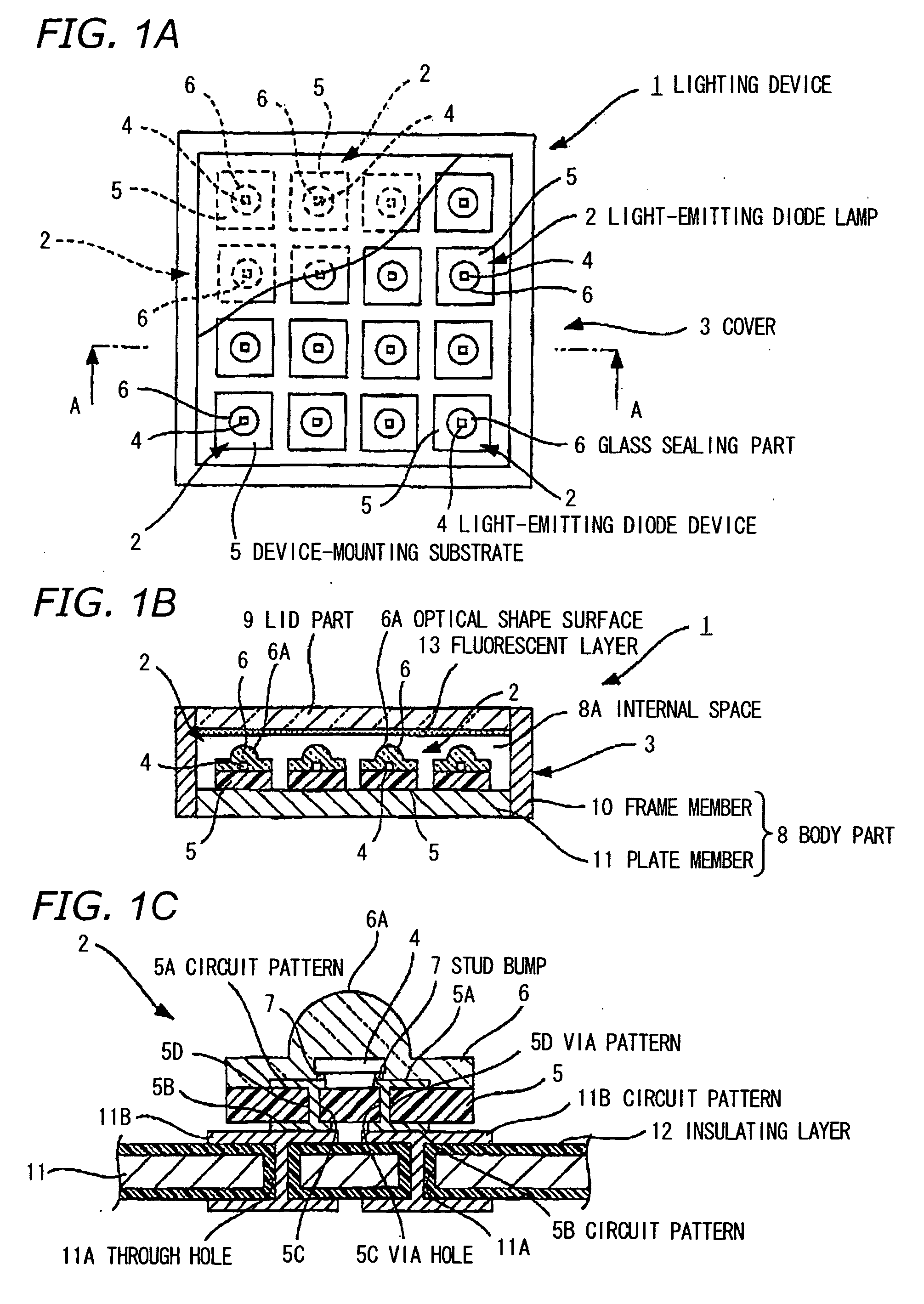
[0047] As shown in FIGS. 1A to 1C, a lighting device 1 approximately comprises plural light-emitting diode lamps 2 for radiating white light to the side of an illuminated object, and a cover 3 with a fluorescent layer 13 to house the light-emitting diode lamps therein.

[0048] Composition of Light-Emitting Diode Lamp

[0049] As shown in FIG. 1A, the light-emitting diode lamps 2 are disposed in lengthwise and crosswise directions on the same plane (in this embodiment four lamps in the lengthwise direction and four lamps in the crosswise direction are disposed). Hereinafter, only a single light-emitting diode lamp 2 will be explained, since every light-emitting diode lamp 2 has almost the same structure. As shown in FIGS. 1B and 1C, the light-emitting diode lamp 2 comprises a light-emitting diode device 4 to emit blue light and a device-mounting substrate 5 mounting the light-emitting diode device 4 thereon, and the light-emitting diode lamp 2...

second embodiment

[0067] In FIG. 3, like components are indicated by using the same numerals as in FIGS. 1A and 1B and the detailed explanation is omitted.

[0068] As shown in FIGS. 3A and 3B, a lighting device 1 of the second preferred embodiment has the features that the lighting device I comprises a light-emitting diode lamp 2A having plural light-emitting diode devices 4 disposed in lengthwise and crosswise directions on the same plane and having a single device-mounting substrate 22 for mounting the plural light-emitting diode devices 4.

[0069] The light-emitting diode devices 4 are sealed by a glass sealing part 24 made of the same material as the glass sealing part 6 in the first preferred embodiment and are arrayed through the glass sealing part 24.

[0070] Advantages of the Second Embodiment

[0071] The advantages obtained by the second preferred embodiment in addition to the advantages (1) and (2) of the first preferred embodiment are as follows.

[0072] The light-emitting diode devices 4 are d...

third embodiment

[0073] In FIG. 4A and 4B, like components are indicated by using the same numerals as in FIG. 1B is and the detailed explanation is omitted.

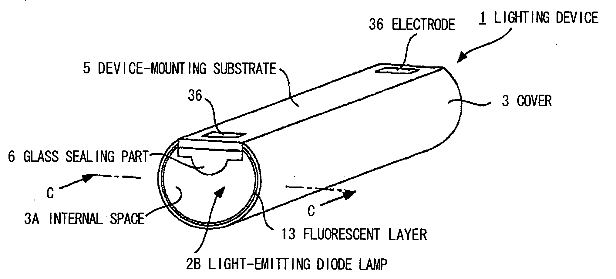
[0074] As shown in FIGS. 4A and 4B, a lighting device 1 of the third preferred embodiment has the features that the lighting device 1 comprises a light-emitting diode lamp 2B having plural light-emitting diode devices 4 (only one device 4 is shown in FIG. 4A) disposed in one direction on the same plane and having a single device-mounting substrate 5 (a ceramic substrate) for mounting the plural light-emitting diode devices 4, and a cover 3 to house the light-emitting diode lamp therein.

[0075] The cover 3 has an internal space 3A to house the light-emitting diode lamp 2B therein, and the cover 3 is composed of a curved surface member which has a curvature on the side of the light-emitting diode lamp 2B and has a shape like a fluorescent tube, and the curved surface member is composed of a translucent member. On the surface of the cover 3 on the...


PUM


Abstract

A lighting device having: a light-emitting diode lamp having a light-emitting diode device sealed by a glass sealing part; and a fluorescent layer disposed on the side of an illuminated object of the light-emitting diode lamp. The fluorescent layer is operable to radiate a wavelength-converted light by being excited by light emitted from the light-emitting diode device.

Description

[0001] The present application is based on Japanese patent application No. 2005-268851, the entire contents of which are incorporated herein by reference. BACKGROUND OF THE INVENTION [0002] 1. FIELD OF THE INVENTION [0003] The present invention relates to a lighting device that is suitable for use in various light sources, e.g., a backlight light source for a liquid-crystal television. [0004] 2. DESCRIPTION OF THE RELATED ART [0005] Recently, a lighting device comprising a light emitting diode (=LED) device has been adopted instead of a cold-cathode fluorescent tube containing a mercury gas therein, from the viewpoints of eliminating the harmful mercury gas on the environment (or human body), preventing component parts from deteriorating by ultraviolet radiation, decreasing the electric power consumption cost due to the use of an inverter circuit, and obtaining a good color reproducibility. [0006] Generally, in this kind of lighting device, to obtain white light, red, green and blue...

Claims


Application Information

Patent Timeline
Patent Type & Authority Applications(United States)
IPC IPC(8): F21V9/16F21V13/12H01L33/32H01L33/42H01L33/50H01L33/54H01L33/56H01L33/60H01L33/62
CPCF21K9/135F21Y2101/02F21V3/00Y10S362/80F21Y2105/001F21K9/56F21Y2103/003F21K9/232F21K9/64F21Y2103/10F21Y2105/10F21Y2115/10H01L2224/16225H01L2924/15174
Inventor YAMAGUCHI, SEIJISUEHIRO, YOSHINOBU
Owner TOYODA GOSEI CO LTD
Why Eureka
Try Eureka