BPSK demodulator circuit using an anti-parallel synchronization loop

a synchronization loop and demodulator technology, applied in the direction of phase-modulated carrier systems, digital transmission, angle demodulation by sloping amplitude/frequency, etc., can solve the problem of squaring loops having a further significant significance, receiving noise is also squared, and cannot work at such high frequencies

Inactive Publication Date: 2007-03-15
QUEENS UNIV OF KINGSTON
View PDF11 Cites 32 Cited by
  • Summary
  • Abstract
  • Description
  • Claims
  • Application Information

AI Technical Summary

Benefits of technology

[0019] The demodulator may also include a selection network for selection of the first and second phase-locked loops. The selection network may have two switches, a comparator, and an inverter. In another embodiment the selection network may have two switches and a differential comparator. The selection network may have a low-pass filter.
[0020] The first and second phase-locked loops may each include a multiplier, or a multiplier and a voltage controlled oscillator. The first and second phase-locked loops may each include a low pass filter and a summing circuit or a voltage summer. The voltage summers may be placed either before or after the low pass filters. A DC offset may be introduced into each phase-locked loop by the voltage summer such that the phase-locked loops have different detected voltage outputs. The first and second phase-locked loops may be interconnected to share a single voltage controlled oscillator.
[0021] The demodulator may include an automatic gain control circuit front end. The demodulator may include an automatic gain control circuit at its input and an error correction at its output. The demodulator may include a voltage summer at the VCO front end. The demodulator may include a voltage summer and a voltage attenuator at the VCO input. The first and second phase-locked loops may each include an amplifier. The first and second phase-locked loops may each include an attenuator.

Problems solved by technology

At microwave frequencies, however, the coherent method is the preferred demodulation technique since the non-coherent technique, such as differential BPSK (DBPSK), strongly depends on the DSP technique for its one-bit delay element, which cannot work at such high frequencies.
Although the squaring device in the squaring loop can remove the data to recover the carrier from the received BPSK signal, the received noise is also squared.
The squaring loop has a further significant disadvantage, which is the need to have the PLL and its VCO running at twice the carrier frequency.
This becomes a problem as the carrier frequency reaches the microwave range: it is more difficult to create a good low-noise oscillator as well as the other PLL components at such high frequencies.
Furthermore, the need for a frequency divider can increase the power consumption of the circuit, since many dividers are known to sink large amounts of power.
This, however, is not always the case.
This may occur at the beginning of the demodulation operation, or in the re-locking process caused by large phase noise in the received BPSK signal.
The switching of the functions between the two loops also causes an inversion on the data output, which the summer cannot recognize.
In either case, the result of the added components is increased complexity, size, and power consumption.

Method used


Image

  • BPSK demodulator circuit using an anti-parallel synchronization loop
  • BPSK demodulator circuit using an anti-parallel synchronization loop
  • BPSK demodulator circuit using an anti-parallel synchronization loop

Examples


Embodiment Construction

[0064] The invention provides a novel circuit to demodulate, or extract, the modulated data from a BPSK-modulated carrier. With easily-integrated characteristics, demodulators of the invention may be used in, for example, INMARSAT™ systems, global positioning systems (GPS), radio frequency identification (RFID) systems, and next-generation digital radio systems.

[0065] As used herein, the term “data” is intended to refer to the information or data, which may be digital, which is modulated in a BPSK signal and recovered or demodulated by a BPSK demodulator circuit of the invention. The terms “demodulator” and “demodulator circuit” are used throughout this disclosure and are intended to be equivalent.

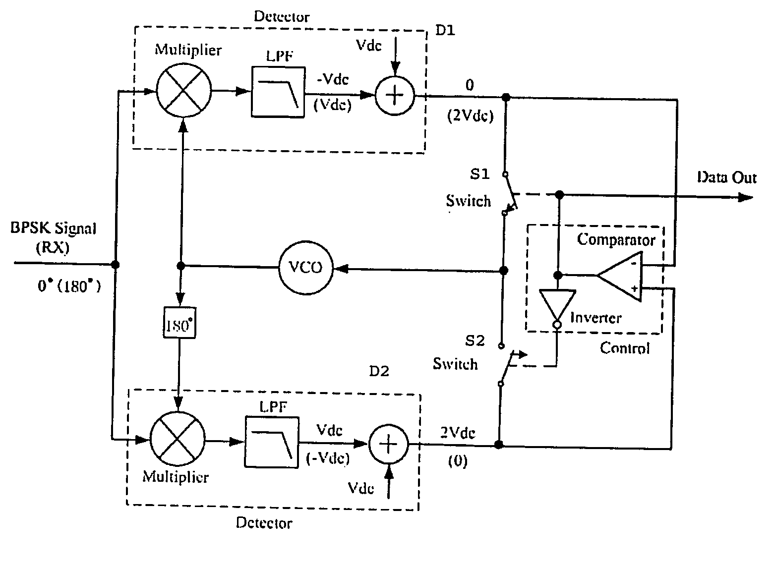
[0066] Referring to FIG. 3.1, the preferred embodiment of the circuit uses two parallel phase-locked loops (PLLs) in which only one of the loops is in lock at any given time. One loop is in phase with the carrier at 0° while the other loop is 180° out of phase. If the incoming BPSK signa...


PUM


Abstract

An anti-parallel loop carrier synchronization circuit for coherent binary phase shift keying (BPSK) demodulation is disclosed. One embodiment comprises an anti-parallel dual phase-locked loop (PLL), which locks the carrier by its upper PLL (0°) and lower PLL (180°) alternately, according to the data bits contained in the received BPSK signal. Demodulation of the data is completed through control of the upper PLL and the lower PLL.

Description

RELATED APPLICATIONS [0001] This application claims the benefit of the filing date of U.S. Patent Application No. 60 / 712,127, filed on Aug. 30, 2005, the contents of which are incorporated herein by reference in their entirety.FIELD OF THE INVENTION [0002] This invention relates to binary phase shift keying (BPSK) based demodulators and applications thereof. BACKGROUND OF THE INVENTION [0003] Binary phase shift keying (BPSK) may use either coherent or noncoherent techniques depending on the performance required and the frequency band in which the system is to work. A coherent demodulator is one in which the phase of the sinusoidal signal carrying the modulated data is determined by the demodulator circuitry and used to recover the data. Noncoherent demodulation techniques do not require any knowledge of the signal phase. Coherent BPSK has approximately a 3 dB advantage over noncoherent BPSK on bit-error-rate (BER) performance. However, coherent BPSK needs to synchronize and recover ...

Claims


Application Information

Patent Timeline
Patent Type & Authority Applications(United States)
IPC IPC(8): H04L27/22H03D3/24
CPCH03D3/26H04L27/2273H04L27/0014
Inventor SAAVEDRA, CARLOSZHENG, YOU
Owner QUEENS UNIV OF KINGSTON
Why Eureka
Try Eureka