Resonant sensor systems and methods with reduced gas interference

a resonant sensor and gas interference technology, applied in chemical methods analysis, instruments, suspensions and porous materials analysis, etc., can solve the problems of reducing the bulk fluid resistance, reducing the detection sensitivity of resonant sensor devices, and limiting the detection sensitivity achieved with dissolved gas,

Inactive Publication Date: 2007-03-15
BIOSCALE
View PDF27 Cites 21 Cited by
  • Summary
  • Abstract
  • Description
  • Claims
  • Application Information

AI Technical Summary

Benefits of technology

[0032] en position, and to prevent fluid flow into the fluid chamber through the inlet port when the inlet valve is in a closed position. In some embodiments, the cartridge includes an outlet valve adapted to allow fluid flow out of the fluid chamber when the outlet valve is in an open position, and to prevent fluid flow out of the fluid chamber when the outlet valve is in a closed position.

Problems solved by technology

However, resonant sensors are also highly sensitive to the presence of gas in a fluid, even if the gas is located relatively distant from the resonant surface of the resonant sensor device, because gases are compressible and, therefore, reduce the bulk fluid resistance to oscillations of the sensor surface.
Bubbles or undissolved gas present significant limitations on the detection sensitivity achieved with resonant sensor devices.
The short durations of time provided by previous techniques did not allow for significant data to be obtained during an experiment.
Such detection instability has prevented the identification of small or moderate changes in the characteristics of a solution.
Furthermore, small or medium-sized molecules in a fluid could not be detected but, rather, only the largest biomolecules could be detected by these systems.

Method used


Image

  • Resonant sensor systems and methods with reduced gas interference
  • Resonant sensor systems and methods with reduced gas interference
  • Resonant sensor systems and methods with reduced gas interference

Examples


examples

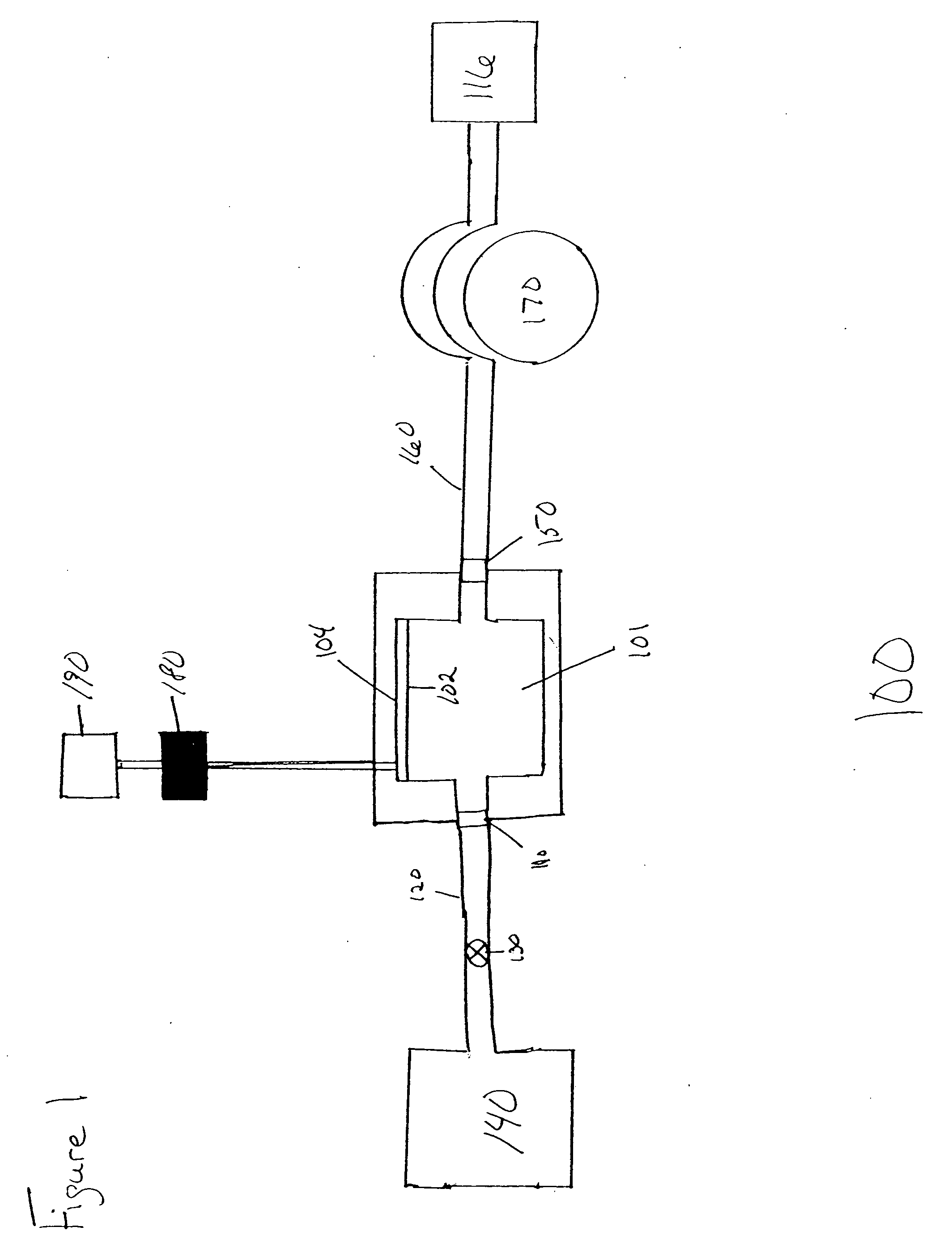
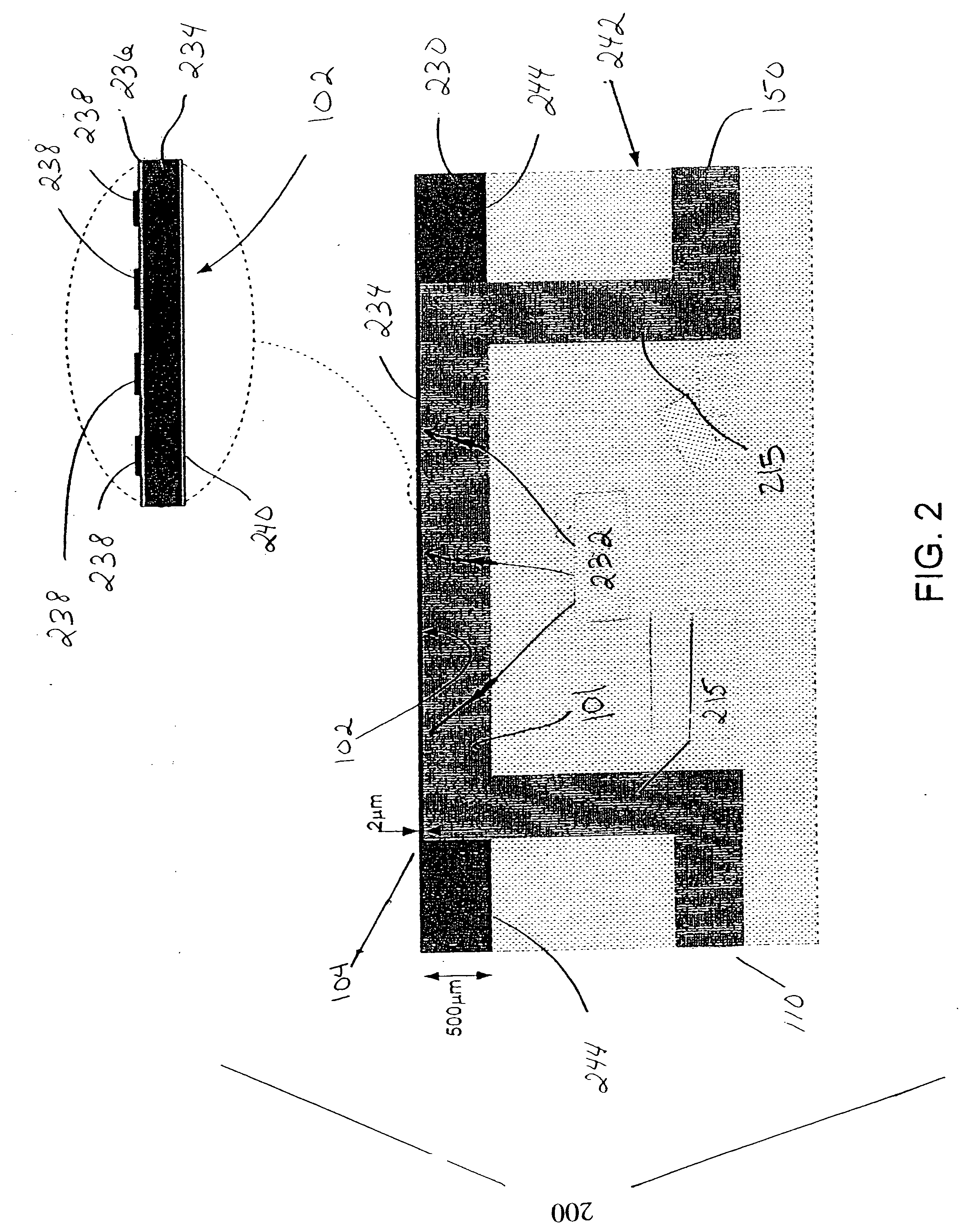
[0135] In one embodiment, the resonant sensor system 100 of FIG. 1 is produced with the resonant sensor device 104 of FIG. 2. The resonant sensor device 104 is a flexural plate wave device. The device is produced from a silicon wafer using microfabrication techniques. A cavity is etched into the silicon wafer to produce a suspended membrane (234) that is approximately 1.6 mm long and 0.4 mm wide. The cavity depth 232 is approximately the wafer thickness, which in this case is 0.5 mm. The membrane 243 is a composite layer consisting of 2 μm of silicon (Si) with 0.5 μm of a piezoelectric aluminum nitride (AlN) (layer 236). Two sets of interdigitated metal electrodes 238 are deposited on top of the AIN layer 236. A time-varying electrical signal is applied to one set of electrodes to generate vibrations in the structure. The vibration characteristics of the resonant device 104 are monitored using the second set of electrodes 238. When a liquid, such as water, is in contact with one sid...


PUM

PropertyMeasurementUnit
water contact angleaaaaaaaaaa
contact angleaaaaaaaaaa
thicknessaaaaaaaaaa

Abstract

A system having reduced gas interference that includes a fluid chamber and a resonant sensor device in fluid communication with a fluid in the fluid chamber. The system includes a fluid control device adapted to change at least one of the fluid flow or pressure within the fluid chamber to achieve substantial wetting of surfaces in proximity to the resonant sensor device. Fluid surfaces of the system can include a material to increase the wettability (e.g., hydrophilicity) of the fluid surfaces.

Description

FIELD OF THE INVENTION [0001] The invention relates to chemical and biological analyte sensing systems. More specifically, the invention relates to resonant sensor systems for measuring or detecting the physical characteristics of fluids or analytes in a fluid sample, and the reduction of gas interference in such systems. BACKGROUND OF THE INVENTION [0002] Resonant sensor systems are microelectromechanical systems (“MEMS”) that can be used to measure the physical characteristics of a substance by detecting changes in resonant frequencies. Typically, resonant sensors utilize the ability of membranes to undergo physical deformation in response to external forces which cause vibrations or rhythmic motion. The membrane deformations are characterized by frequencies that are altered by the fluid medium surrounding the membrane, or by substances binding to the membrane that change the membrane's mass. By detecting frequencies in particular media or under particular conditions, resonant sen...

Claims


Application Information

Patent Timeline
Patent Type & Authority Applications(United States)
IPC IPC(8): G01N30/96
CPCB82Y15/00B82Y30/00G01N2291/0257G01N2291/0256G01N29/036
Inventor MASTERS, BRETT P.MILLER, MICHAEL F.
Owner BIOSCALE
Why Eureka
Try Eureka