Detector

a detection device and detector technology, applied in the field of sensors, can solve the problems of low signal-noise ratio, poor light-receiving efficiency, low temperature burn on the human body, etc., and achieve the effect of suppressing the decrease in signal-noise ratio, reducing the amount of light emission for each light-emitting section, and improving light-receiving efficiency

Inactive Publication Date: 2007-03-15
SHARP KK
View PDF1 Cites 22 Cited by
  • Summary
  • Abstract
  • Description
  • Claims
  • Application Information

AI Technical Summary

Benefits of technology

[0041] That is, the detector has at least two or more light-receiving sections, and this makes it possible to enhance the light-receiving efficiency without the necessity of increasing the light emission amount in the light-emitting section.
[0042] Even when the wearing position is displaced by body motion, selection and combination of a plurality of reception signals makes it possible to suppress decrease in signal-noise ratio in the reception signals.
[0043] Moreover, since the light emission amount for each light-emitting section can be reduced, it becomes possible to decrease the possibility of causing low-temperature burn on the human body in long-time wearing.
[0044] Moreover, since the light-receiving area of each light-receiving section can be reduced, it becomes possible to reduce the probability of picking up any disturbance light, which is other than pulse wave signals. Therefore, the signal-noise ratio in the reception signals can be increased.
[0045] Moreover, the proportion of the AC component in a reception signal increases, and this can increase the signal-noise ratio in the reception signals.
[0046] Moreover, it becomes possible to determine whether or not the wearing position of the detector is optimum. In addition, it is possible to display the correction direction for an optimum wearing position, and therefore users can easily correct the wearing position.

Problems solved by technology

Consequently, since the proportion of the DC component is relatively larger than the proportion of the AC component in the light emitted from the light-emitting section in the transmission type, detection of pulse waves has a problem of a low signal-noise ratio.
In the reflection-type ring sensor as disclosed in JP 2002-224088 A, light-receiving efficiency is poor since reflected light or diffused light is received, and therefore it is necessary to increase the amount of light emitted from the light-emitting section or to enlarge a light-receiving area of the light-receiving section corresponding to the light-emitting section.
Increasing the amount of light may cause low-temperature burn on the human body in long-time wearing.
In the case of enlarging the receiving area of a single light-receiving section, the probability of picking up disturbance light, which is not a measuring object, increases, and this causes the problem of a low signal-noise ratio.
Moreover, in detection of pulse waves, there is a problem of the low signal-noise ratio depending on wearing positions.
In this case, the AC component decreases, which causes the problem of the low signal-noise ratio.
Moreover, with a single light-receiving section, it is difficult to determine whether or not a wearing position is optimum and it is impossible to detect the direction in which a wearing position is displaced.

Method used


Image

  • Detector
  • Detector
  • Detector

Examples


embodiment 1

[0057] (Embodiment 1)

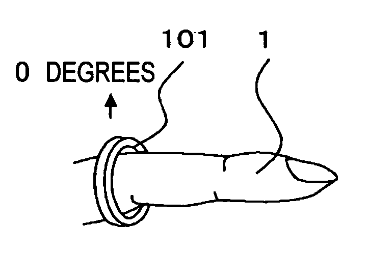
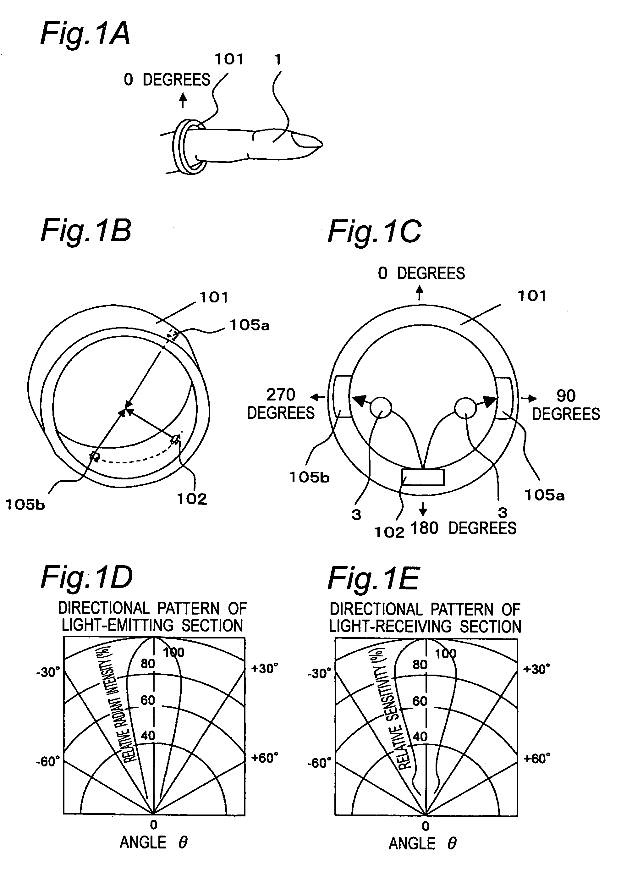
[0058]FIGS. 1A to 1E are views about a ring sensor in an embodiment 1.

[0059] As shown in FIG. 1A, a ring sensor 101, which is a finger ring-type ring, is worn on the base of a finger 1. A ring size is appropriately selected according to the size of a finger of each user so that the inner circumferential surface of the ring is constantly in close contact with the finger.

[0060]FIGS. 1B and 1C show the inner circumferential surface and the cross section of the ring sensor. On the inner circumferential surface, there are a light-emitting section 102 formed from a light-emitting diode, and first and second light-receiving sections 105a, 105b formed from photodiodes. The light-emitting section 102 has a light-emitting diode for emitting red light and a light-emitting diode for emitting infrared light.

[0061]FIG. 1D shows an example of the directional patterns of the light-emitting section and the light-receiving section. The light-emitting section 102 and the respec...

embodiment 2

[0097] (Embodiment 2)

[0098]FIGS. 3A to 3D are views about a ring sensor in an embodiment 2.

[0099] It is to be noted that as for the structure of the embodiment 2, explanation about structure components identical to those in the embodiment 1 shown in FIGS. 1A to 1E and FIGS. 2A to 2B is omitted and their differences are mainly described.

[0100] In FIGS. 3A and 3B, a light-emitting section 202 is formed on the inner circumferential surface of a ring sensor 201, and first and second light-receiving sections 205a, 205b are formed at positions symmetric to a light-emitting axis of the light-emitting section 202. More specifically, the first and second light-receiving sections 205a, 205b are placed at positions facing each other on the inner circumferential surface of the ring sensor 201.

[0101] Moreover, a light-emitting point of the light-emitting section 202 and respective light-receiving points of the first and second light-receiving sections 205a, 205b are placed at tracks different...

embodiment 3

[0105] (Embodiment 3)

[0106]FIG. 4A is a perspective view showing a ring sensor in a worn state in an embodiment 3 of the present invention, and FIG. 4B is a transverse sectional view showing the ring sensor.

[0107] It is to be noted that as for the structure of the embodiment 3, explanation about structure components identical to those in the embodiments 1 and 2 shown in FIGS. 1A to 1E and FIGS. 3A to 3D is omitted and their differences are mainly described.

[0108] First and second light-receiving sections 305a, 305b are respectively divided into light-receiving regions a, b, c and A, B, C.

[0109] The respective light receiving regions are formed along the inner circumferential surface of the ring in a circumferential direction in the order of a, b, c and A, B, C from the farthest side from the a light-emitting section 302.

[0110] In FIG. 4B, the light-emitting section 302 is formed on the inner circumferential surface of a ring sensor 301, and the first and second light-receiving s...


PUM


Abstract

A pair of light-receiving sections are placed at positions symmetric to a light-emitting axis of a light-emitting section on the inner circumferential surface in close contact with a finger, and each light-receiving section is composed of a plurality of light receiving regions so that by selecting a signal of the light receiving region which maximizes a reception signal, the propriety and the correction direction of a wearing position are displayed. According to the ring sensor, it becomes possible to enhance light-receiving efficiency of the light-receiving section and to increase a signal-noise ratio. It also becomes possible to facilitate wearing of the ring sensor at an optimum position.

Description

CROSS-REFERENCE TO RELATED APPLICATIONS [0001] This nonprovisional application claims priority under 35 U.S.C. §119(a) on Patent Application No(s). 2005-245972 filed in Japan on Aug. 26, 2006, the entire contents of which are hereby incorporated by reference. BACKGROUND OF THE INVENTION [0002] The present invention relates to a sensor for optically measuring biological information in a noninvasive manner. [0003] Conventionally, ring sensors which have a light-emitting section and a light-receiving section provided on the inner circumferential surface of a ring have been used for optically detecting pulse waves. [0004] It is known that among hemoglobin in the blood, oxyhemoglobin and reduced hemoglobin are different in light absorption and transmission characteristics depending on wavelengths of light. The oxyhemoglobin absorbs infrared light more than red light, whereas the reduced hemoglobin has an optical characteristic to absorb red light more than infrared light. [0005] Therefor...

Claims


Application Information

Patent Timeline
Patent Type & Authority Applications(United States)
IPC IPC(8): A61B5/00
CPCA61B5/14552A61B5/6838A61B5/6826A61B5/14
Inventor OISHI, YOSHIHIRO
Owner SHARP KK
Why Eureka
Try Eureka