Method of determining FET junction temperature

a temperature and junction technology, applied in the direction of resistance/reactance/impedence, instruments, heat measurement, etc., can solve the problems of difficult to determine the real time current and power of an fet, and difficult to measure the temperature at the junction (tsub>j/sub>) of the fet directly

Active Publication Date: 2007-03-15
DELPHI TECH IP LTD
View PDF2 Cites 20 Cited by
  • Summary
  • Abstract
  • Description
  • Claims
  • Application Information

AI Technical Summary

Benefits of technology

[0006] In accordance with the subject invention the real time current and power of a field effect transistor (FET) is ascertained by determining the temperature TJ at the junction of the FET in a stable region of operation where the junction temperature minus the measured temperature (TJ−Tth) is nearly constant accordance with a first set of equations until a step change occurs in successive m

Problems solved by technology

It is difficult to determine the real time current and power of an FET because the resistance (RDS) of the FET can vary significantly with temperature.
However, it is diffic

Method used


Image

  • Method of determining FET junction temperature
  • Method of determining FET junction temperature
  • Method of determining FET junction temperature

Examples


Embodiment Construction

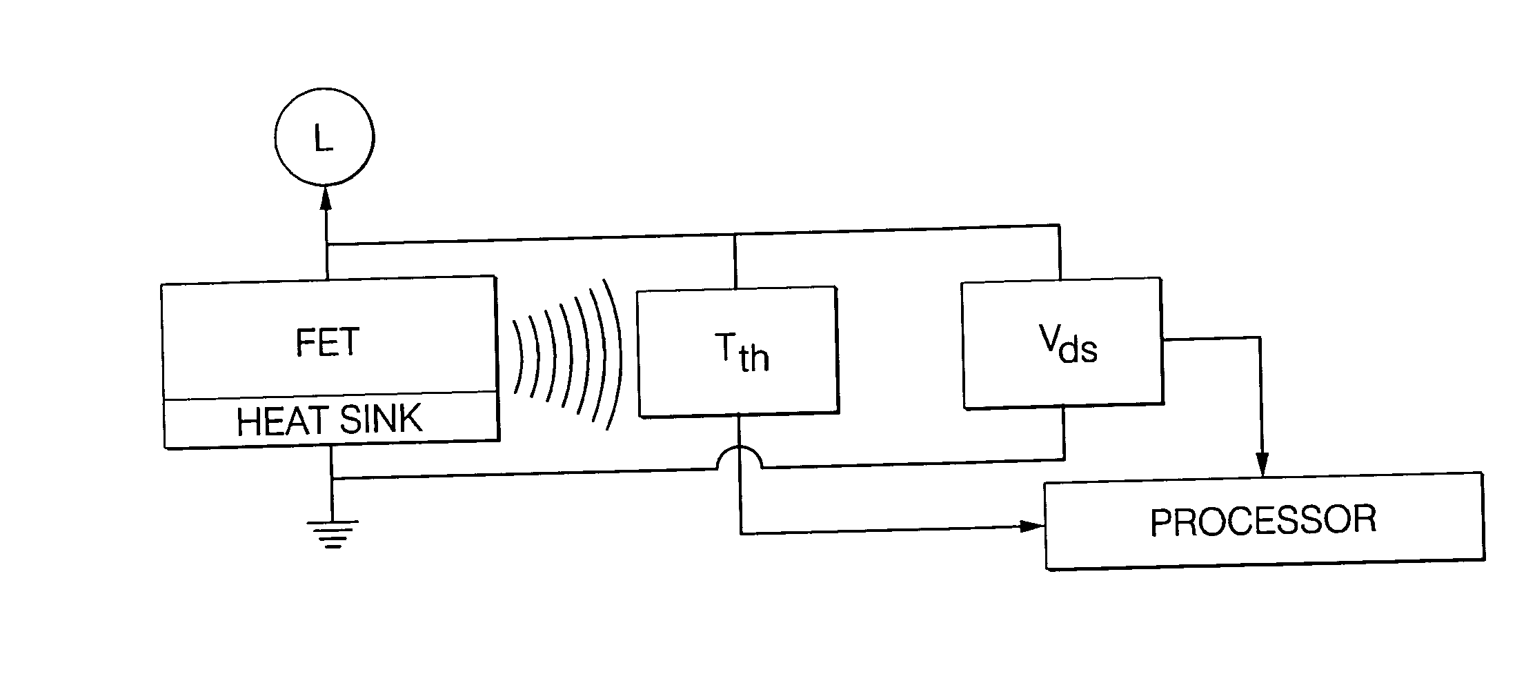
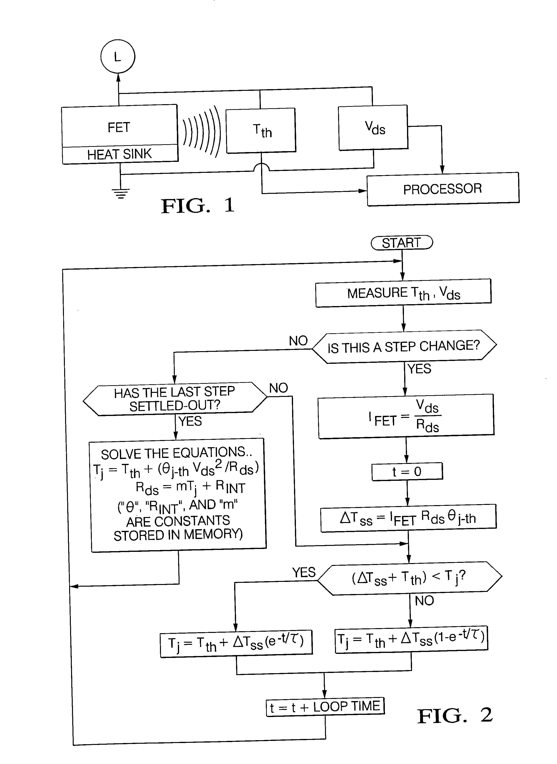
[0014] Referring to the FIG. 1, a system for determining the current through a field effect transistor (FET) is illustrated. In a power control system, the field-effect transistor (FET) functions as a switch to control power to a load (L). A thermsistor is mounted in close thermal proximity to the FET for measuring or inferring the temperature Tth adjacent the junction of the FET. The mechanical packaging of the FET would include a heat sink for dissipating heat generated by the FET. Also included is a voltage meter (VDS) and appropriate circuitry for measuring the drain-to-source voltage (VDS) of the FET.

[0015] The system is distinguished by a processor or digital core responsive to Tth and VDS and for storing characteristics of the FET and a thermal model of the system hardware for determining the temperature TJ at the junction of the FET in a stable region of operation where TJ−Tth is nearly constant accordance with a first set of equations. The processor is further responsive t...


PUM


Abstract

A processor is responsive to a thermistor temperature Tth adjacent a FET functioning as a switch to control power to a load (L) and responsive to drain-to-source voltage (VDS) of the FET. The processor stores the characteristics of the FET and a thermal model of the system hardware and uses a first set of equations to determine the temperature TJ at the junction of the FET in a stable region of operation where TJ−Tth is nearly constant. The processor is further responsive to a step change in successive measurements of VDS indicative of a lag of Tth relative to TJ thereby rendering Tth unusable in the first set of equations and immediately determines an initial FET current IFET. The processor then resolves TJ based upon a second set of equations comprising TJ=Tth+ΔTSS(1−e−t/τ) when ΔTSS+Tth≧TJ and TJ=Tth+ΔTSS(e−t/τ) when ΔTSS+Tth≦TJ where τ is a constant and ΔTSS is the steady-state temperature difference between the TJ and Tth at the initial FET current IFET determined in accordance with ΔTSS=IFET2RDSθJ−th.

Description

BACKGROUND OF THE INVENTION [0001] 1. Field of the Invention [0002] A method and system for determining the electrical resistance of a field-effect transistor (FET). [0003] 2. Description of the Prior Art [0004] A field-effect transistor (FET) is often used as a switch in power electronics to control current to larger electrical load, such as an electrical motor. As electrical current (I) flows through the FET, a drain-to-source voltage (VDS) is created by virtue of the FET on resistance (RDS). It is useful to know the current and power (P) so that the current provided to the load can be directly and accurately controlled and to prevent exceeding the operating temperature of the FET. [0005] The drain-to-source voltage (VDS) of an FET can be measured directly with well known electrical devices. It is difficult to determine the real time current and power of an FET because the resistance (RDS) of the FET can vary significantly with temperature. In some instances, the resistance (RDS) ...

Claims


Application Information

Patent Timeline
IPC IPC(8): G01K1/00
CPCG01K7/01G01R31/2628G01K7/42G01K7/22
Inventor TURNER, STEVEN R.ZAKARIA, MOHAMMED
Owner DELPHI TECH IP LTD
Why Eureka
Try Eureka