Suntrap self-regulating solar greenhouse

a solar greenhouse and self-regulating technology, applied in the field of solar greenhouses, can solve the problems of large single cost to growers, lack of sufficient light levels and day-length, deleterious effects on propagation rates, etc., and achieve the effect of restricting temperature fluctuations and rapid heat loss

Inactive Publication Date: 2007-03-22
STEVENS MICHAEL MAURICE
View PDF3 Cites 34 Cited by
  • Summary
  • Abstract
  • Description
  • Claims
  • Application Information

AI Technical Summary

Problems solved by technology

As a part of increasingly sophisticated growing techniques, it was determined that large fluctuations in temperature had deleterious effects on propagation rates, as did lack of sufficient light levels and day-length.
Problems inherent in the current “state-of-the-art” commercial greenhouse design, primarily variations of a polyethylene film-covered “tunnel” of rigid hoops, include rapid heat-loss at night or during inclement weather, necessitating the input of heat from fossil fuels and resulting in the largest single cost to the grower, lack of storage for excess thermal energy created during sunny days, thereby necessitating the “dumping” of excess heat to the outside, a wasteful endeavor, and the necessity of providing some method of partially covering the tunnel greenhouse on sunny days in late spring, summer and early fall to prevent the plants inside from “burning”.

Method used


Image

  • Suntrap self-regulating solar greenhouse
  • Suntrap self-regulating solar greenhouse
  • Suntrap self-regulating solar greenhouse

Examples


Embodiment Construction

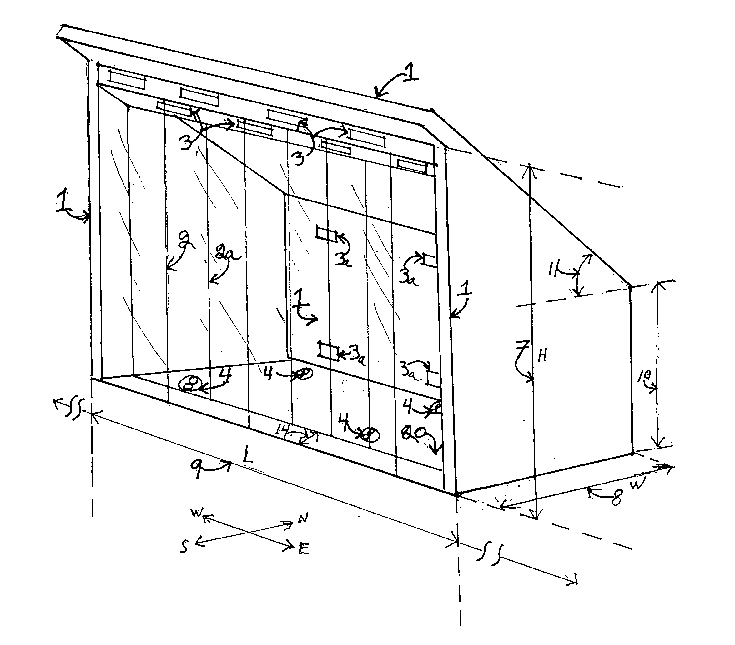
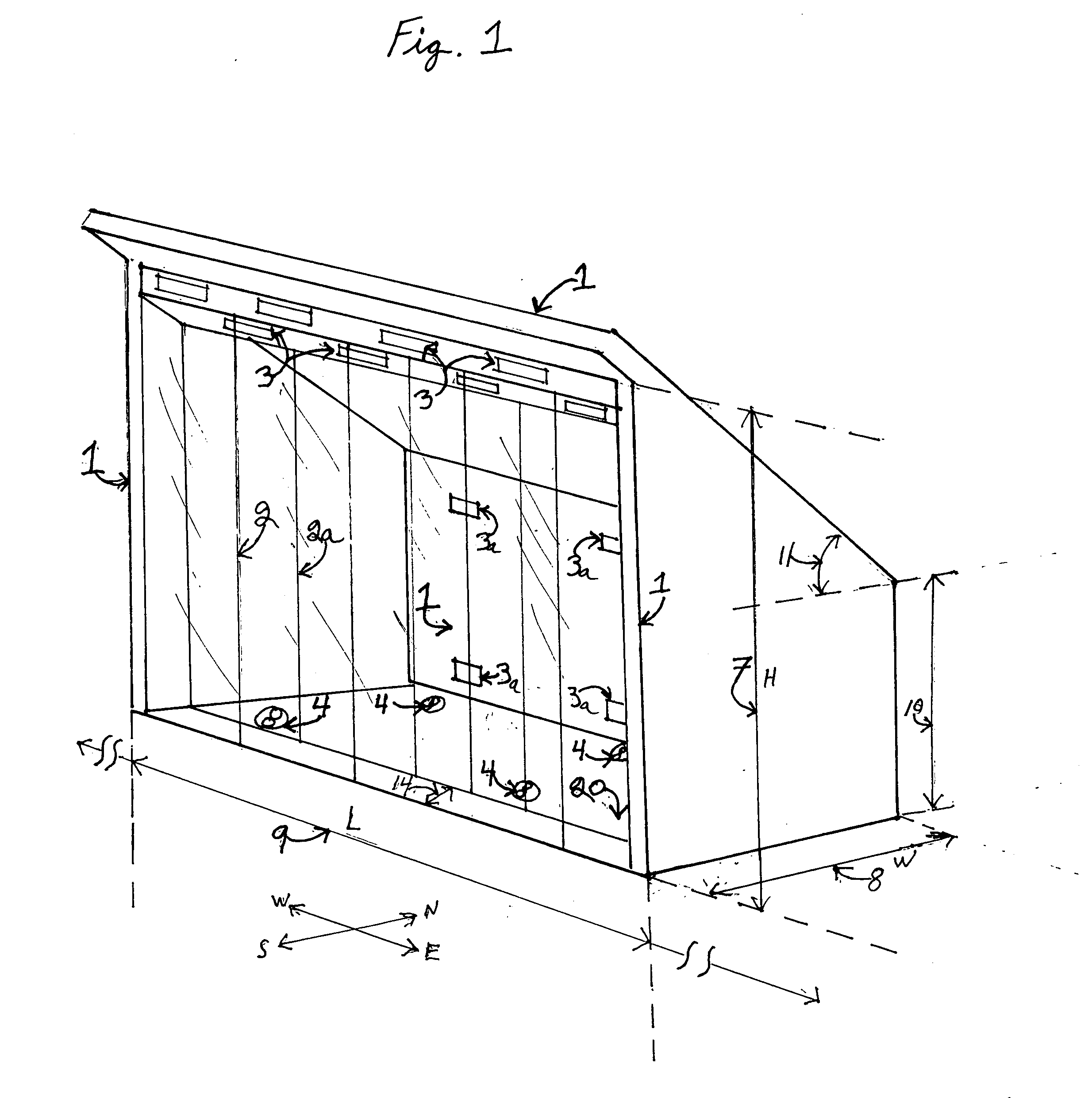
[0012] Referring to the drawings and to FIG. 1, a perspective view from the southeast, discloses the basic design concepts of the solar greenhouse structure of the present invention. The floor 20 is bordered on three sides by a heavily insulated thermal shell 1, which, in the preferred embodiment, is formed of east and west trapezoidal walls, a short rectangular north wall, a large, rectangular sloping roof facing north at a 6 / 12 pitch, said floor 20 to be bordered on the fourth (south) side by tall solar curtain walls 2&2a, in the preferred embodiment of glass and appropriate support means, which extend from floor 20 to shell 1 (roof) and connect shell 1 (east and west walls), forming two distinct surfaces, generally planar and vertical, with an obvious separation 14 between outer solar wall 2& inner solar wall 2a. The overall configuration of the structure is likened to a simple “shed” design, the geometry of said design being an essential element of the functionality of the inven...


PUM


Abstract

A self-regulating solar-heated-and-cooled greenhouse consisting of a thermally-insulated opaque shell, generally formed by a floor supporting east, north, and west-oriented walls supporting a northerly-facing sloping roof, leaving the southern exposure of said shell “open”, said shell incorporating means of regulating the admission or expulsion of air to the greenhouse. Said “open” south face to be sealed-over by a solar energy collecting system comprised of two parallel light-admitting curtain-wall systems, generally vertical in orientation and planar in configuration, with a space between said wall systems forming an enhanced thermal break and of sufficient distance so as to effect periodic maintenance, and incorporating means of regulating admission or expulsion of air to the greenhouse. Said greenhouse further incorporating means of directing excess thermal energy collected during daylight hours into appropriate storage systems either within or without the confines of said greenhouse, and further incorporating means of providing insulation for the south-facing solar-wall systems at night or during inclement weather.

Description

BACKGROUND AND OBJECTS OF THE INVENTION [0001] Commercial greenhouses have long provided a means for producing food crops and flowering plants in temperate-to-cold climate zones where seasonal changes greatly affect the propagation of green plants. Greenhouses were first constructed to shelter plants from temperatures below which they could not survive. As a part of increasingly sophisticated growing techniques, it was determined that large fluctuations in temperature had deleterious effects on propagation rates, as did lack of sufficient light levels and day-length. Current commercial greenhouse operations employ a wide variety of techniques to restrict temperature fluctuations within the greenhouse and also provide artificial lighting to supplement sunlight during late-fall, winter, and early spring. Problems inherent in the current “state-of-the-art” commercial greenhouse design, primarily variations of a polyethylene film-covered “tunnel” of rigid hoops, include rapid heat-loss ...

Claims


Application Information

Patent Timeline
Patent Type & Authority Applications(United States)
IPC IPC(8): A01G9/00
CPCA01G9/14Y02A40/25Y02P60/12
Inventor STEVENS, MICHAEL MAURICE
Owner STEVENS MICHAEL MAURICE
Why Eureka
Try Eureka