Vaporized fuel purge system

a technology of vaporized fuel and purge gas, which is applied in the direction of combustion air/fuel air treatment, electric control, machines/engines, etc., can solve the problems of excessive current fuel concentration, and inability to maintain constant fuel concentration of purge gas

Inactive Publication Date: 2007-03-22
TOYOTA JIDOSHA KK
View PDF6 Cites 4 Cited by
  • Summary
  • Abstract
  • Description
  • Claims
  • Application Information

AI Technical Summary

Benefits of technology

[0019] A first aspect of the invention relates to a vaporized fuel purge system including: a fuel injection valve that injects a fuel in an internal combustion engine; an exhaust gas sensor that generates an output indicative of an exhaust air-fuel ratio in the internal combustion engine; an FAF calculation device that calculates, based on the output of the exhaust gas sensor, a feedback correction coefficient applied to a fuel injection amount so that the exhaust air-fuel ratio matches a target air-fuel ratio; a canister that adsorbs a vaporized fuel produced in a fuel tank; a purge mechanism that allows a purge gas that contains the vaporized fuel to flow from the canister into the internal combustion engine; a sharp-change-condition detecting device that detects a sharp-change condition in which a fuel concentration of the purge gas changes at a rate higher than a reference rate; a concentration updating base value setting device that sets a concentration updating base value based on the feedback correction coefficient by a predetermined process; a process changing device that changes the predetermined process such that the concentration updating base value is made larger in the sharp-change condition than in a non-sharp-change condition; a fuel concentration updating device that updates a fuel concentration of the purge gas using the concentration updating base value; a purge correction coefficient calculation device that calculates a purge correction coefficient that is used to eliminate an influence of the vaporized fuel based on the fuel concentration of the purge gas; and a fuel injection amount calculation device that calculates a final fuel injection amount by reflecting the feedback correction coefficient and the purge correction coefficient on a basic fuel injection amount.
[0020] In this case, the concentration update base value is set based on the feedback correction coefficient for correcting the exhaust air-fuel ratio to the target air-fuel ratio so as to update the fuel concentration of purge gas. The feedback correction coefficient reflects the deviation of the exhaust air-fuel ratio from the target air-fuel ratio, that is, the deviation of the learned value from the actual fuel concentration of purge gas during purging. According to the invention, the fuel concentration of purge gas is updated based on the deviation of the learned value from the actual value of the fuel concentration. Also, in the sharp-change condition in the fuel concentration of purge gas, the concentration update base value is made larger than in a non-sharp-change condition. Thus, the invention makes it possible to constantly and promptly converge the learned value of the fuel concentration of purge gas to the actual fuel concentration value.
[0022] In this case, the update of the fuel concentration of the purge gas is allowed only when the concentration update base value that has been set based on the feedback correction coefficient deviates is out of the dead band. That is, in the sharp-change condition, upper and lower threshold values of the dead band are changed so as to cause the concentration update base value to easily deviate from the dead band. Accordingly, the fuel concentration of the purge gas is more likely to be updated in response to a sharp change in the fuel concentration, which enables the updating to more accurately and timely reflect changes in the actual fuel concentration of the purge gas.
[0024] The above structure allows the upper and lower threshold values of the dead band to shift in the same direction in response to a sharp change in the fuel concentration. In this case, the width of the dead band is hardly narrowed, thus maintaining its hunting prevention function.
[0028] In this case, a warm start of the internal combustion engine is detected based on the parameter correlated with the engine temperature upon start of the engine, and when a warm start is thus detected, the detecting of the sharp-change condition is prohibited. Note that since a large amount of the vaporized fuel is generated within the fuel tank when the engine has been warm-started, the fuel concentration of purge gas hardly decreases sharply during purging. According to the above structure, therefore, it is possible to effectively prevent execution of the process that copes with a sharp change in the fuel concentration of purging gas when such a sharp change does not actually occur.
[0034] In this case, the initial value of the purge correction coefficient is set on the assumption that the fuel concentration of purge gas is higher when the engine temperature upon start is higher. Note that, the higher the temperature, the more likely the fuel adsorbed within the canister will be purged and the fuel within the fuel tank will be vaporized. That is, the higher the engine temperature upon its start, the higher the concentration of the purge gas generated immediately after start of purging will be. According to the above structure, therefore, it is possible to set the initial value of the fuel concentration of purging gas so that it more precisely corresponds to the actual fuel concentration of the purging gas.

Problems solved by technology

Specifically, when the feedback correction coefficient FAF becomes larger than the reference value by 2% or more during purging of vaporized fuel, it is considered that the current fuel concentration is excessively low.
Meanwhile, when the feedback correction coefficient FAF becomes smaller than the reference value by 2% or more, it is considered that the current fuel concentration is excessively high.
The fuel concentration of purge gas cannot be maintained constant during operation of the internal combustion engine.
However, if the fuel concentration changes sharply, the learned value is likely to largely deviate from the actual fuel concentration of purge gas.
This related-art device, therefore, may cause the problems to be described below.
In this case, the learned value of the fuel concentration may fail to timely approximate the actual fuel concentration.
Thus, there may be the case that the learned value of the fuel concentration exceeds the actual fuel concentration, resulting in overshooting.
Thus, the aforementioned related-art device has difficulties in learning the fuel concentration of purge gas timely and accurately.

Method used


Image

  • Vaporized fuel purge system
  • Vaporized fuel purge system
  • Vaporized fuel purge system

Examples


first embodiment

[0048] First Embodiment

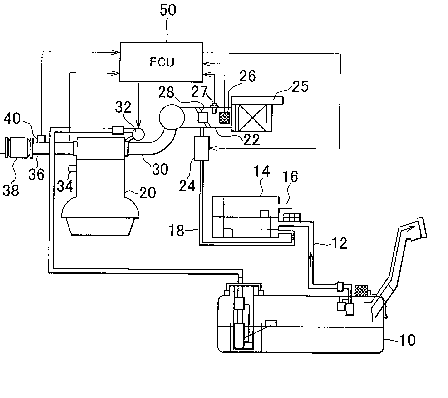
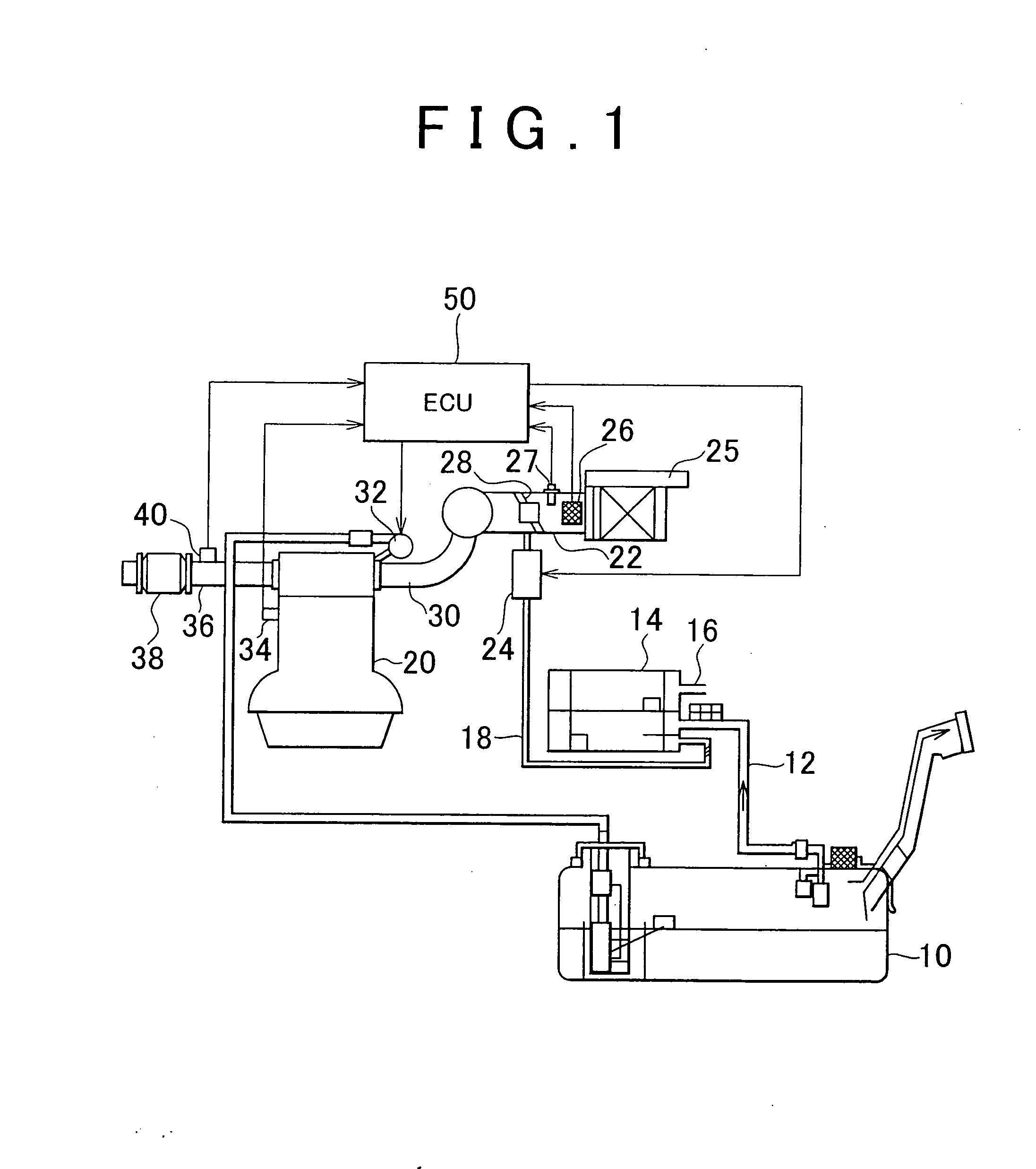
[0049]FIG. 1 shows a structure of a first embodiment of the invention. A vaporized fuel purge system includes a fuel tank 10 communicated with a canister 14 through a vapor passage 12. The canister 14 is provided with an air inlet 16, and communicated with an intake air passage 22 of an internal combustion engine 20 via a purge passage 18. The canister 14 contains activated carbon for adsorbing the vaporized fuel generated within the fuel tank 10.

[0050] The purge passage 18 is provided with a purge control valve 24 which controls a flow rate of gas flowing therethrough. The purge control valve 24 is duty controlled to a desired opening degree.

[0051] The intake air passage 22 is provided with an air cleaner 25 at its one end, and both an airflow meter 26 for detecting an intake air amount Ga and an intake air temperature sensor 27 for detecting an intake air temperature THA are provided downstream of the air cleaner 25. The intake air passage 22 is also provi...

second embodiment

[0126] Second Embodiment

[0127] The second embodiment of the invention will be described referring to FIG. 7. In the second embodiment, the system according to the first embodiment is employed such that the ECU 50 executes the routine shown in FIG. 7 instead of the one shown in FIG. 6.

[0128] In the first embodiment, the possibility of sharp changes in the fuel concentration is determined based on the fuel concentration of purge gas. However, in the case where the internal combustion engine 20 is started in a sufficiently warm state, a large amount of vaporized fuel has been already generated within the fuel tank 10 so as to be supplied to the canister 14. Accordingly, the fuel concentration of purge gas hardly decreases during purging.

[0129] In the system according to the second embodiment, a determination is made whether the internal combustion engine 20 has been warm-started or cold-started. If it is determined that the engine 20 has been cold-started, the vapor concentration cor...

third embodiment

[0137] Third Embodiment

[0138] The third embodiment of the invention will be described referring to FIG. 8. In the third embodiment, the system according to the first or the second embodiment is employed such that the ECU 50 executes the routine shown in FIG. 8 instead of steps 130, 132 and 136 of FIGS. 6 and 7.

[0139] In the first or the second embodiment, the time the fuel cell concentration of purge gas converges to a specific level, i.e., the time a sharp decrease in the fuel concentration of purge gas ends, is estimated based on the total purge time (updating count tCFGPG). Meanwhile in the third embodiment, the convergence timing can be estimated further accurately based on the temperature of the internal combustion engine 20 or the total purge amount, as will be described below.

[0140] As aforementioned, the fuel concentration of purge gas sharply decreases temporarily as purging proceeds, and thereafter converges to a specific level. This convergence timing is correlated with...


PUM


Abstract

A feedback correction coeficient used to perform feedback-control of the fuel injection amount based on the air-fuel ratio of exhaust gas is calculated. A concentration updating based value is set based on the deviation of the oscillation center of the feedback correction coefficiect, and a vapor concentration correction coefficient corresponding to the fuel concentration of purge gas is updated using the concentration updating base value. During the period where the fuel concentration of purge gas is expected to sharply decrease, the concentration updating base value is increased.

Description

INCORPORATION BY REFERENCE [0001] The disclosure of Japanese Patent Application No. 2005-271320 filed on Sep. 20, 2005 including the specification, drawings and abstract is incorporated herein by reference in its entirety. BACKGROUND OF THE INVENTION [0002] 1. Field of the Invention [0003] The invention relates to a vaporized fuel purge system, and particularly, to a vaporized fuel purge system suitable for purging vaporized fuel generated within a fuel tank of a vehicle. [0004] 2. Description of the Related Art [0005] Patent Application Publication No. H7-259615 discloses the device that adsorbs vaporized fuel generated in the fuel tank so as to be held in the canister, and purges the vaporized fuel into the intake passage during operation of the internal combustion engine. In order to constantly maintain the control accuracy of the air-fuel ratio in the aforementioned device, the fuel injection amount is required to be reduced during purging by the amount corresponding to that of ...

Claims


Application Information

Patent Timeline
Patent Type & Authority Applications(United States)
IPC IPC(8): F02D41/14F02M25/08
CPCF02D41/0042F02M25/089F02D41/1454F02D41/0045
Inventor OSANAI, AKINORI
Owner TOYOTA JIDOSHA KK
Why Eureka
Try Eureka