Cooling structure, heatsink and cooling method of heat generator

a heat generator and cooling structure technology, applied in the direction of cooling/ventilation/heating modification, semiconductor device details, semiconductor/solid-state device details, etc., can solve the problems of poor long-term reliability of a thermal grease that is coated to reduce the contact thermal resistance between the heat transfer vessel or the insulating substrate and the heat generator, and poor heat dissipation characteristics. , to achieve the effect of excellent heat dissipation characteristics

Active Publication Date: 2007-03-22
MITSUBISHI ELECTRIC CORP
View PDF35 Cites 47 Cited by
  • Summary
  • Abstract
  • Description
  • Claims
  • Application Information

AI Technical Summary

Benefits of technology

[0017] In a cooling structure and cooling method according to the above-aspects, since a heatsink made of a metal foil having the flexibility is adhered through an insulating adhesive layer to a surface of a heat generator and a heat dissipation structure having such a configuration is disposed in a fluid flow path so that a cooling fluid and the heatsink may directly come into contact, a cooling structure that is lightweight and compact and excellent in the heat dissipation characteristics can be obtained.
[0018] Furthermore, since a heatsink acc

Problems solved by technology

As mentioned above, since in an existing cooling structure a heat generator is attached to a heat transfer vessel or on an insulating substrate, the contact thermal resistance is generated between the heat transfer vessel or the insulating substrate and the heat generator to be poor in the heat dissipation characteristics.
Furthermore, there is a problem as well in that the long-term reliability of a thermal grease that is coated to decrease the contact thermal resistance between the heat transfer vessel or the insulating substrate and the heat generator is poor.
Still furthermore, in the case of the heat generator being an electronic component, since a volume an

Method used


Image

  • Cooling structure, heatsink and cooling method of heat generator
  • Cooling structure, heatsink and cooling method of heat generator
  • Cooling structure, heatsink and cooling method of heat generator

Examples


example 2

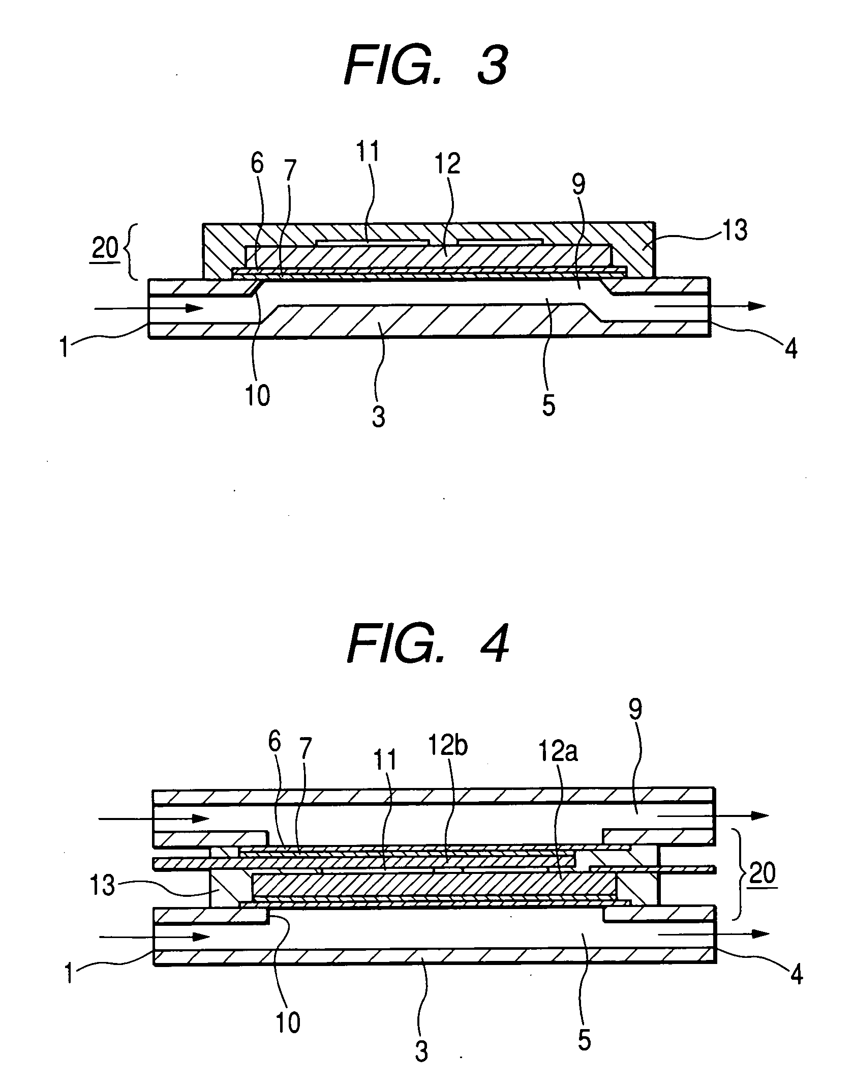
[0067]FIG. 3 is sectional configurational diagram schematically showing a cooling structure according to embodiment 2 of the invention.

[0068] The embodiment 2 is one where the heat generator 8 according to the embodiment 1 is more specified and constituted of, as shown in FIG. 3, a semiconductor element 11 and a heat spreader 12 disposed on one surface of the semiconductor element 11. To such a heat generator, on a heat spreader surface on a side opposite to the semiconductor element 11, through an insulating adhesive layer 6, a heatsink 7 made of a flexible metal foil is adhered to form a heat dissipation structure 2.

[0069] The heat spreader 12 plays a role of fastening the semiconductor element 11, a role of energizing from or to the semiconductor element 11 and a role of thermally diffusing heat generated at the semiconductor element 11 and transmitting the heat through an insulating adhesive layer 6 to the heatsink 7 and is made of metal. Preferably, the heat spreader 12 is de...

embodiment 3

[0087]FIGS. 5A and 5B are configurational diagrams schematically showing a cooling structure according to embodiment 3 of the invention, FIG. 5A being a planar configurational diagram showing a heat transfer surface of a heatsink and FIG. 5B being a sectional configurational diagram thereof. Furthermore, in FIG. 5B, a diagram obtained by enlarging a round mark portion of a heat dissipation structure 2 is shown together.

[0088] In a cooling structure according to embodiment 3, on a surface of the heatsink of a heat dissipation structure in the embodiment 1 or 2, a sequence of fine recesses 15 having a rectangular cross section and connected in a direction that intersects with a direction of a flow of a fluid are disposed. The fine recesses 15 has an asymmetric shape in cross section along a flow direction of the cooling fluid.

[0089] In case that a recessed portion is proved on a surface where a heat is expanded, a cool fluid peels off from an upstream side thereof from the recessed ...

embodiment 4

[0143]FIG. 10 is a sectional configurational diagram schematically showing a heatsink according to an embodiment 4 of the invention. In FIG. 10, an enlarged diagram of a round mark portion of the heatsink is shown together.

[0144] A heatsink 70 according to the embodiment 4, as shown in FIG. 10, includes a cooling fluid intake port 1, a heat transfer vessel 30 in which a flow path is formed and a cooling fluid output port 4, an inner surface wall of the flow path of the heatsink 70 being provided with fine recesses 15 described in the embodiment 3. An improvement effect in the heat dissipation characteristics due to the fine recesses 15, which was described in the embodiment 3, as obvious from experimental results shown in FIG. 7, is not specific to the configuration where, in a heatsink made of a flexible metal foil, the fine recesses 15 are disposed but also effective in the case where the fine recesses 15 are disposed on an arbitrary heat transfer surface.

[0145] The fine recess ...


PUM


Abstract

A cooling structure includes a heat dissipation structure 20 having a heat generator 8 and a heatsink 7 that is adhered through an insulating adhesive layer 6 to at least a surface of the heat generator 8 that faces a cooling fluid 9 and made of a metal foil having the flexibility; and a fluid flow path 5 that is disposed outside of the heat dissipation structure 20 so that the cooling fluid 9 flowing inside thereof and the heatsink 7 may directly come into contact. Furthermore, on a surface of the heatsink that directly comes into contact with the cooling fluid 9, a fine recess 15 is disposed.

Description

BACKGROUND [0001] 1. Technical Field [0002] The present invention relates to a cooling structure for cooling a heat generator constituted of electronic parts and a heatsink. Furthermore, the invention relates to a cooling method of the heat generator. [0003] The cooling structure indicates a cooling structure that cools heat generated by a heat generator with a cooling fluid and includes a heat generator and a fluid flow path through which the cooling fluid flows. The heatsink indicates a structure that thermally couples with the heat generator and directly comes into contact with the cooling fluid to heat exchange with the cooling fluid to dissipate the heat of the heat generator to the cooling fluid. [0004] 2. Description of Related Art [0005] An existing cooling structure has a configuration where a heat generator is disposed to a heatsink that includes, for instance, a cooling fluid intake port, a heat transfer vessel provided with a flow path therein and a cooling fluid output ...

Claims


Application Information

Patent Timeline
IPC IPC(8): H05K7/20
CPCH01L23/473H05K7/20272H01L2924/0002H01L2924/00
Inventor IPPOUSHI, SHIGETOSHIYAMADA, AKIRAMAEKAWA, HIROTOSHIYABUNAKA, FUMIHARU
Owner MITSUBISHI ELECTRIC CORP
Why Eureka
Try Eureka