Clock signal generating and distributing apparatus

a clock signal and apparatus technology, applied in the direction of generating/distributing signals, oscillating generators, pulse automatic control, etc., can solve the problem that the desired signal cannot be generated, and achieve the effect of high precision

Inactive Publication Date: 2007-03-22
FUJITSU LTD
View PDF5 Cites 12 Cited by
  • Summary
  • Abstract
  • Description
  • Claims
  • Application Information

AI Technical Summary

Benefits of technology

[0009] It is therefore an object of the present invention to provide a distributive clock generating and distributing apparatus that can generate and distribute a clock signal of high precision even in a high-frequency region of several giga hertz and higher.
[0011] Therefore another object of the present invention is to provide a distributive VCO-type clock generating and distributing apparatus, in which VCOs oscillate in the same phase, and which can generate a clock signal of a desired frequency and distribute a clock signal of a high frequency to each part within a chip more stably.

Problems solved by technology

Additionally, a wire that connects oscillation nodes of VCOs is considered to be a length of several 100 μm or longer, and its inductor component cannot be ignored in a high-frequency region reaching 20 GHz, leading to a problem such that the VCOs do not oscillate in the same phase, and a signal of a desired frequency cannot be generated.

Method used


Image

  • Clock signal generating and distributing apparatus
  • Clock signal generating and distributing apparatus
  • Clock signal generating and distributing apparatus

Examples


Embodiment Construction

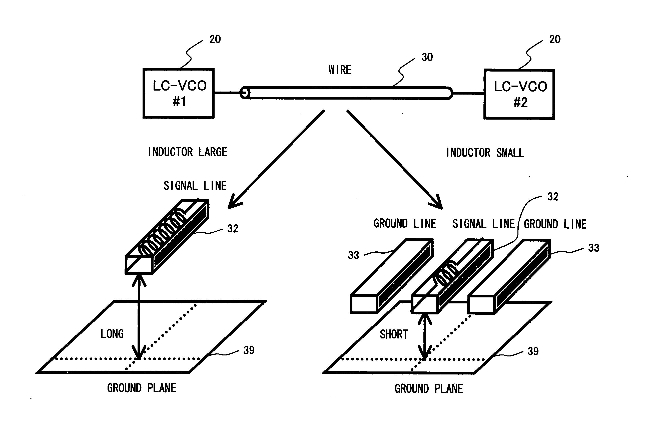
[0033]FIG. 4 shows a distributive VCO-type clock generating and distributing apparatus that adopts LC resonant oscillators as VCOs, and a first preferred embodiment of the present invention according to which the influence of an inductance of a wire between oscillation nodes of LC resonant oscillators (20) is reduced by inserting a resistor element between the oscillation nodes of the LC resonant oscillators (20). In the embodiment shown in this figure, the oscillation nodes of the LC resonant oscillators (20) are connected with a one-dimensional wire. However, the oscillation nodes can be connected also with wires in the shape of a mesh.

[0034] This preferred embodiment is configured by LC resonant oscillators #1 (20) and #2 (20), which respectively supply a clock to circuit blocks (91) and (92) via buffers (81) and have the same physical configuration, and a PLL composed of an LC resonant oscillator #0 (20) having the same configuration as the LC resonant oscillators #1 (20) and #...


PUM


Abstract

LC resonant voltage control oscillators are adopted as voltage control oscillators for the purpose of providing a clock generating and distributing apparatus that can generate and distribute a clock signal of high precision even in a high-frequency region of several giga hertz or higher, and of providing a distributive VCO-type clock generating and distributing apparatus in which voltage control oscillators oscillate in the same phase, and which can generate a clock signal of a desired frequency and distributes a high-frequency clock signal to each part within a chip more stably even in a high-frequency region reaching 20 GHz. Furthermore, an inductor component of a wire connecting the oscillation nodes of the oscillators is made relatively small, or the LC resonant oscillators are oscillated in synchronization by using injection locking, whereby the LC resonant voltage control oscillators stably oscillate in the same phase.

Description

CROSS-REFERENCE TO RELATED APPLICATIONS [0001] This application is based upon and claims the benefit of priority from the prior Japanese Patent Application No. 2005-271058 filed on Sep. 16, 2005, the entire contents of which are incorporated herein by reference. BACKGROUND OF THE INVENTION [0002] 1. Field of the Invention [0003] The present invention relates to an apparatus for generating and distributing a clock signal of high speed and high precision for a high-speed interface circuit, a processor, and an analog or digital circuit that requires a clock signal of a high frequency. [0004] 2. Description of the Related Art [0005] In recent years, frequencies of clock signals have been improving with the rapid advance of semiconductor integrated circuits. As a result, a timing constraint condition required for a clock signal has been becoming strict. Furthermore, with an increase in the scale of an LSI, it is also difficult to distribute a clock signal of high precision to each part w...

Claims


Application Information

Patent Timeline
Patent Type & Authority Applications(United States)
IPC IPC(8): H03B5/08H03B5/18
CPCG06F1/04G06F1/10H03L7/24H03L7/099H03L7/0805
Inventor KANDA, KOUICHITAMURA, HIROTAKAYAMAGUCHI, HISAKATSUOGAWA, JUNJI
Owner FUJITSU LTD
Why Eureka
Try Eureka