Electrophoresis device, electronic apparatus, and driving method of electrophoresis device

a technology of electrophoresis device and electronic apparatus, which is applied in the direction of static indicating devices, instruments, etc., can solve the problems of unipolarity of the transistor used for driving the electrophoresis device, affecting the display, and prone to voltage shifting by leakage, so as to prevent deterioration of display quality

Active Publication Date: 2007-03-22
E INK CORPORATION
View PDF9 Cites 12 Cited by
  • Summary
  • Abstract
  • Description
  • Claims
  • Application Information

AI Technical Summary

Benefits of technology

[0011] An advantage of the invention is that it provides to prevent deterioration of the display quality under the influence of a voltage drop of a pixel electrode in an electrophoresis device which makes electrophoretic particles migrate by keeping the voltage of the pixel electrode constant to change the voltage of a common electrode.
[0012] According to an aspect of the invention, an electrophoresis device includes a first substrate having a plurality of pixel electrodes formed on a surface thereof, a second substrate having a common electrode formed on a surface thereof and disposed to face the pixel electrodes, and an electrophoretic layer disposed between the pixel electrodes and the common electrode. The electrophoresis device makes electrophoretic particles migrate by keeping the potential of each pixel electrode constant and changing a voltage to be applied to the common electrode. The device also includes a voltage control means which supplies a voltage whose minimum voltage is not less than V3 and whose maximum voltage are not more than V4 to the common electrode, in a case where a potential which appears in each pixel electrode when a minimum voltage V1 is supplied to a voltage supply means to each pixel electrode is set to V3 and a potential which appears in each pixel electrode when a maximum voltage V2 is supplied to the voltage supply means is set to V4.
[0013] Further, the first substrate may further include a thin film semiconductor circuitry layer.
[0014] As a result, it is possible to prevent deterioration of display quality which may be caused by migration of electrophoretic particles as the potential of a pixel electrode shifts by wiring resistance, etc.
[0015] Further, according to still another aspect of the invention an electronic apparatus includes the above-described electrophoresis device as a display unit. Here, the “electronic apparatus” includes all apparatuses provided with a display unit using the display by an electrophoretic material, and more specifically, includes display apparatuses, TV apparatuses, electronic papers, clocks, electronic calculators, portable telephones, personal digital assistants (PDAs), etc. Further, the concept of the “apparatus” also include, arbitrary things, for example, flexible sheet-like or film-like objects, things belonging to real estate, such as wall surfaces to which these objects are bonded, and things belonging to movable bodies, such vehicles, flying bodies, and vessels.
[0016] According to another aspect of the invention, there is provided a method of an electrophoresis device including a first substrate having a plurality of pixel electrodes formed on a surface thereof, a second substrate having a common electrode formed on a surface thereof and disposed to face the pixel electrodes, and an electrophoretic layer disposed between the pixel electrodes and the common electrode. The electrophoresis device makes electrophoretic particles migrate by keeping the potential of each pixel electrode constant and changing a voltage to be applied to the common electrode. The method includes supplying a voltage whose minimum voltage is not less than V3 and whose maximum voltage are not more than V4 to the common electrode, in a case where a potential which appears in each pixel electrode when a minimum voltage V1 is supplied to a voltage supply means to each pixel electrode is set to V3 and a potential which appears in each pixel electrode when a maximum voltage V2 is supplied to the voltage supply means is set to V4.

Problems solved by technology

In the electrophoresis device, it is necessary to apply a bipolar voltage between the two electrodes in order to move the electrophoretic particles reversibly, However, a transistor used for driving of the electrophoresis device has unipolarity.
However, the above method has a problem in that, since the voltage to be applied to the pixel electrode shifts due to factors, such as a voltage drop by wiring resistance and leak, display may be disturbed.
Since wiring lines on the side of the pixel electrodes generally are formed as minutely as possible in order to increase the density of pixels, a voltage drop by wiring resistance and the voltage shifting by leak are apt to occur.
Since the electrophoresis device does not have threshold characteristics, the electrophoretic particles may migrate also in response to such slight electric field, which causes deterioration of display quality.
This is because electrophoretic particles cannot have sufficient responsiveness if the pulse period is not more than 50 ms, and display switching time become too long if the pulse period is not less than 1000 ms.

Method used


Image

  • Electrophoresis device, electronic apparatus, and driving method of electrophoresis device
  • Electrophoresis device, electronic apparatus, and driving method of electrophoresis device
  • Electrophoresis device, electronic apparatus, and driving method of electrophoresis device

Examples


embodiment 1

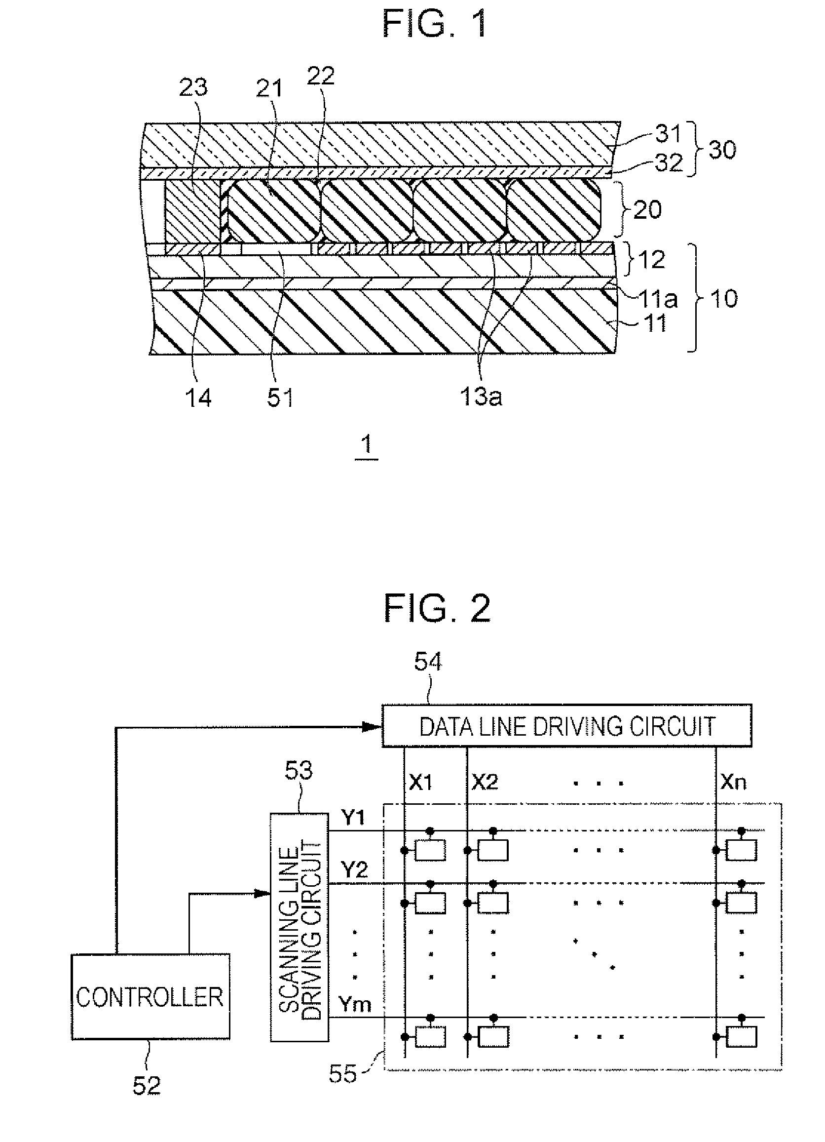
[0027]FIG. 1 is a view showing the section of an electrophoresis display device 1 that is an example of the electrophoresis device according to the invention. As shown in this figure, the electrophoresis display device 1 is roughly composed of a first substrate 10, an electrophoretic layer 20, and a second substrate 30.

[0028] Tn the first substrate 10, a thin film semiconductor circuitry layer 12 is formed on a flexible substrate 11 as an insulating underlying substrate which forms an electric circuit. The thickness of the first substrate 10, for example, is desirably 25 μm or more from the viewpoint of the physical strength of the substrate in forming a thin film circuit, and it is desirably 200 μm or less from the viewpoint of flexibility of the substrate.

[0029] The flexible substrate 11 is, for example, a polycarbonate substrate having a film thickness of 200 μm. On this flexible substrate 11, a semiconductor circuit layer 12 is laminated (bonded) via an adhesive layer 11a made...


PUM


Abstract

An electrophoresis device includes a first substrate having a plurality of pixel electrodes formed on a surface thereof, a second substrate having a common electrode formed on a surface thereof and disposed to face the pixel electrodes, and an electrophoretic layer disposed between the pixel electrodes and the common electrode. The electrophoresis device makes electrophoretic particles migrate by keeping the potential of each pixel electrode constant and changing a voltage to be applied to the common electrode. The device also includes a voltage control means which supplies a voltage whose minimum voltage is not less than V3 and whose maximum voltage are not more than V4 to the common electrode, in a case where a potential which appears in each pixel electrode when a minimum voltage V1 is supplied to a voltage supply means to each pixel electrode is set to V3 and a potential which appears in each pixel electrode when a maximum voltage V2 is supplied to the voltage supply means is set to V4.

Description

BACKGROUND [0001] 1. Technical Field [0002] The present invention relates to an electrophoresis device, an electronic apparatus, and a driving method of the electrophoresis device. [0003] 2. Related Art [0004] An electrophoresis device is constructed by sealing an electrophoretic dispersion liquid containing one or more kinds of electrophoretic particles and an electrophoretic dispersion medium between a set of opposed electrode plates at least one of which is transparent. By applying a voltage between two electrodes, the electrophoretic particles move in the electrophoretic dispersion medium and the distribution thereof change accordingly. This changes optical reflection characteristics, enabling display of information. [0005] In the electrophoresis device, it is necessary to apply a bipolar voltage between the two electrodes in order to move the electrophoretic particles reversibly, However, a transistor used for driving of the electrophoresis device has unipolarity. [0006] As a t...

Claims


Application Information

Patent Timeline
Patent Type & Authority Applications(United States)
IPC IPC(8): G09G3/34
CPCG09G3/344G09G2320/0223G09G2310/06G09G2300/08
Inventor KAWAI, HIDEYUKI
Owner E INK CORPORATION
Why Eureka
Try Eureka