Magnetic element

a technology of magnetic elements and elements, applied in the field of magnetic elements, can solve the problems of high required power, easy crosstalk, and high required power, and achieve the effects of reducing the size of the element and power saving, and avoiding crosstalk

Inactive Publication Date: 2007-03-22
KK TOSHIBA
View PDF5 Cites 44 Cited by
  • Summary
  • Abstract
  • Description
  • Claims
  • Application Information

AI Technical Summary

Problems solved by technology

However, only a few devices are designed in consideration of magnetization control.
However, in the magnetization control method using a magnetic field, since a nanolevel magnetic material is hard to select because of the nature of the magnetic field, crosstalk readily occurs.
Also, the smaller the size becomes, the higher the required power is.
Hence, size reduction of the element and power saving are expected to be difficult.
However, in the technique of Jpn. Pat. Appln. KOKAI No. 2004-006775, it is difficult to operate signals of magnetization reversal and signal processing independently.
Hence, devices are hard to integrate.

Method used


Image

  • Magnetic element
  • Magnetic element
  • Magnetic element

Examples


first embodiment

[5] First Embodiment

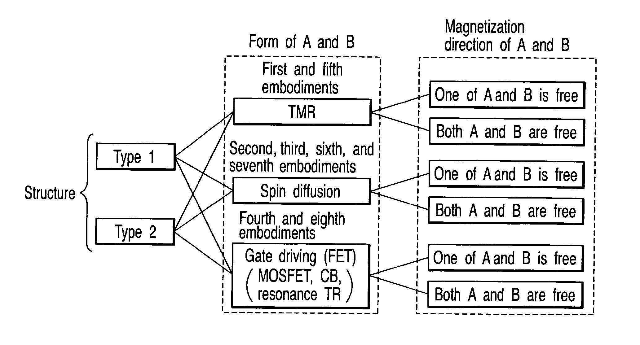
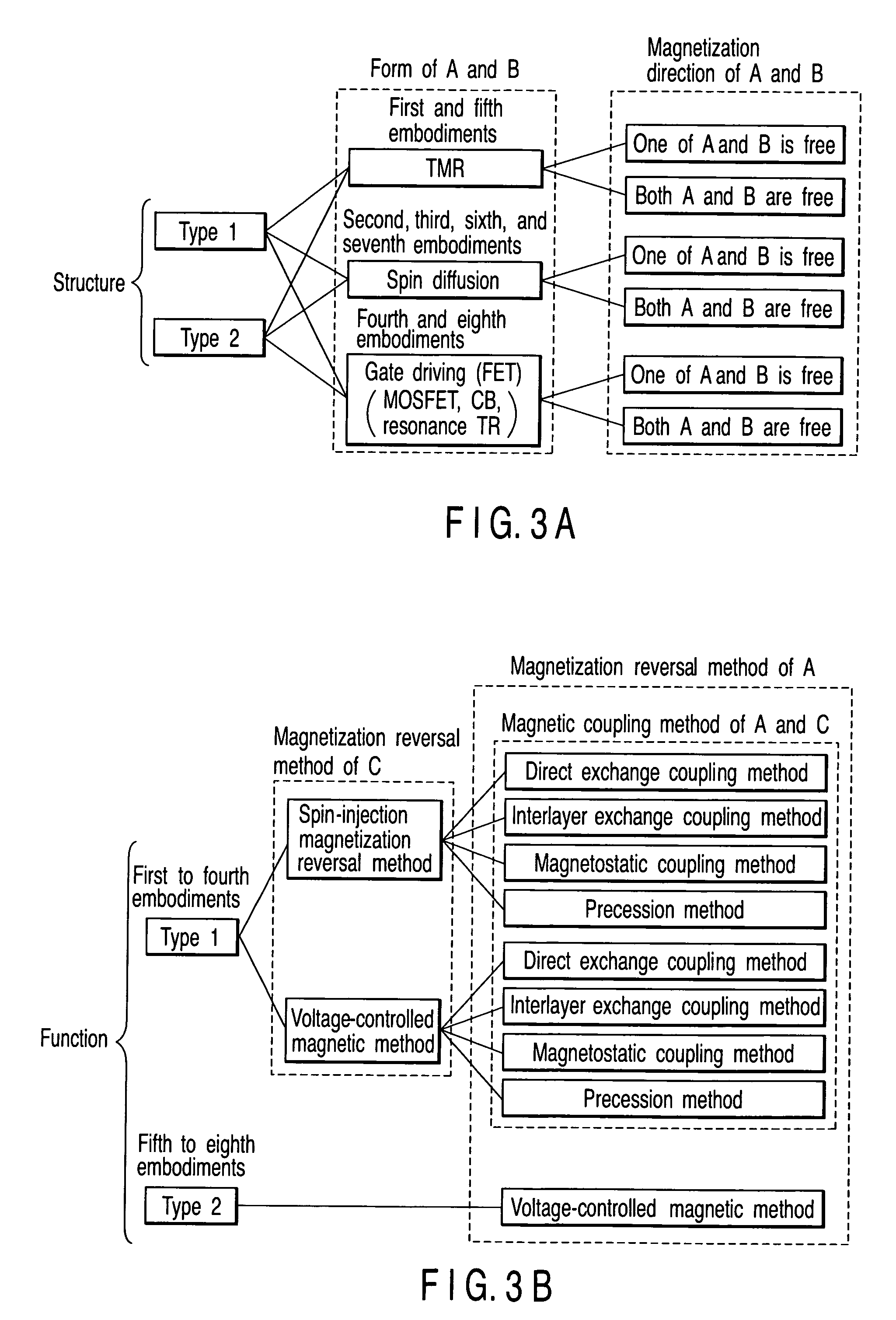
[0101] In the first embodiment, an example of a TMR magnetic element of type 1 will be described.

[5-1] Structure

[0102]FIGS. 15A to 15H are schematic views showing a magnetic element according to the first embodiment of the present invention. The structure of the magnetic element according to the first embodiment of the present invention will be described below.

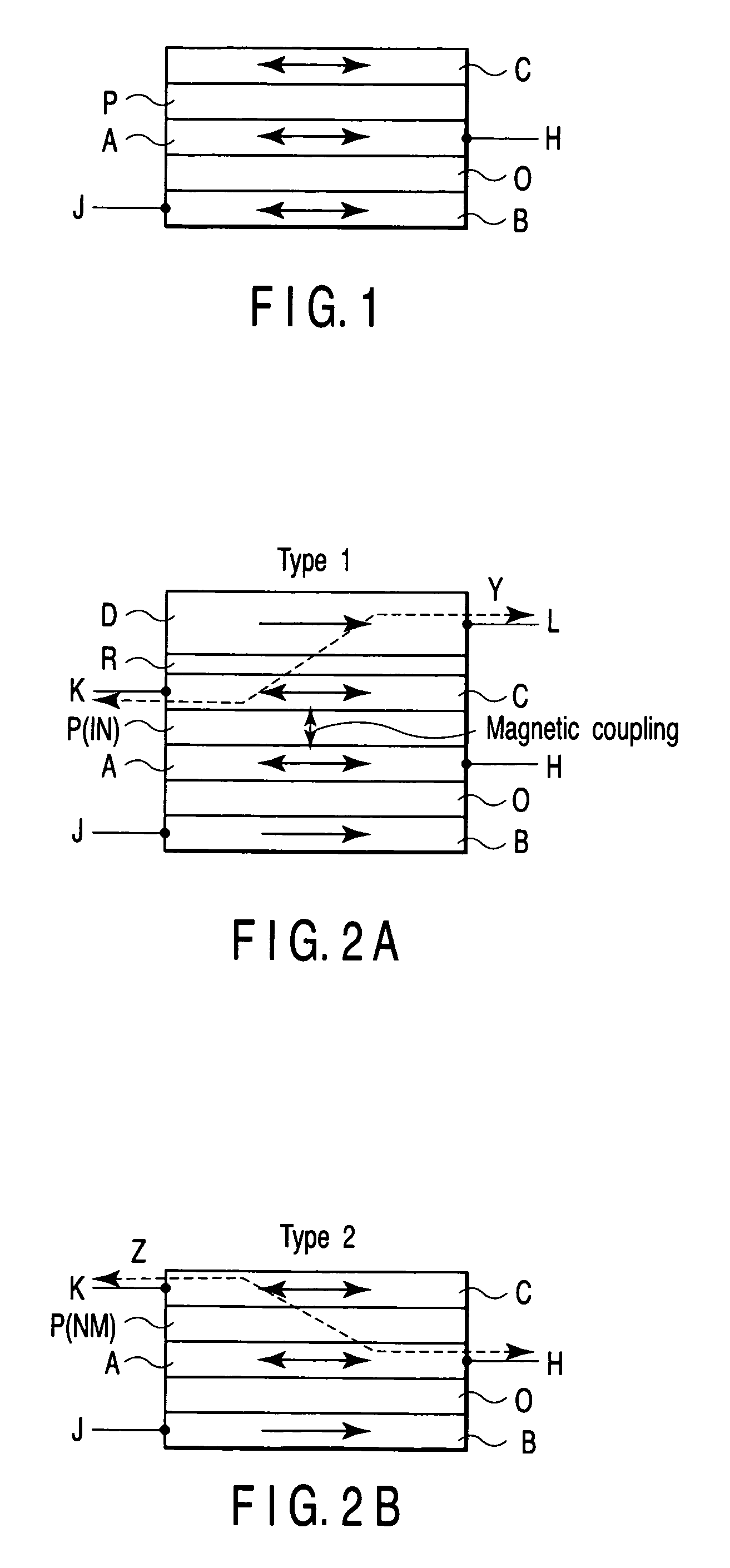
[0103] As shown in FIG. 15A, the magnetic element according to the first embodiment comprises a channel layer O including a tunnel barrier layer TB, magnetic electrodes A and B which sandwich the channel layer O, a magnetic layer C provided on the side of the magnetic electrode A, a nonmagnetic or magnetic insulating layer IN (intermediate layer P) provided between the magnetic layer C and the magnetic electrode A, a magnetic layer D provided on a side of the magnetic layer C opposite to the magnetic electrode A, an intermediate layer R made of a metal or insulator and provided between the magnetic laye...

second embodiment

[6] Second Embodiment

[0156] In the second embodiment, an example of a spin diffusion magnetic element of type 1 will be described. In the second embodiment, voltage generation by the spin diffusion effect is used as a means for obtaining the output signal between magnetic electrodes A and B.

[6-1] Structure

[0157]FIGS. 16A to 16D are schematic views showing a magnetic element according to the second embodiment of the present invention. The structure of the magnetic element according to the second embodiment of the present invention will be described below.

[0158] As shown in FIG. 16A, the magnetic element of the second embodiment is largely different from that of the first embodiment in that a metal layer is used as a channel layer O, and electrodes I1 and I2 are connected to the channel layer O.

[0159] More specifically, the magnetic electrodes A and B are provided in contact with the channel layer O made of a metal. The magnetic electrodes A and B are arranged adjacent on the sam...

third embodiment

[7] Third Embodiment

[0175] In the third embodiment, an example of a spin diffusion magnetic element of type 1 will be described, as in the second embodiment. In the third embodiment, a compound layer is provided.

[7-1] Structure

[0176]FIGS. 17A to 17D are schematic views showing a magnetic element according to the third embodiment of the present invention. The structure of the magnetic element according to the third embodiment of the present invention will be described below.

[0177] As shown in FIG. 17A, the magnetic element of the third embodiment is largely different from that of the second embodiment in that a compound layer Q is provided between a channel layer O and magnetic electrodes A and B.

[0178] More specifically, the compound layer Q containing at least one of oxygen, nitrogen, and fluorine is provided in contact with the channel layer O made of a metal. The magnetic electrodes A and B are provided in contact with the compound layer Q. The magnetic electrodes A and B ar...


PUM

PropertyMeasurementUnit
thicknessaaaaaaaaaa
thicknessaaaaaaaaaa
sizeaaaaaaaaaa

Abstract

A magnetic element includes a channel layer, a first magnetic electrode which is in contact with the channel layer, a second magnetic electrode which is in contact with the channel layer and is insulated from the first magnetic electrode, a first intermediate layer which is provided adjacent to the first magnetic electrode and has a first insulating layer, a first magnetic layer which is provided in contact with a surface of the first intermediate layer on an opposite side to a surface contacting the first magnetic electrode to transfer magnetization to the first magnetic electrode, a first electrode which is connected to the first magnetic electrode, and a second electrode which is connected to the second magnetic electrode, at least one of the first electrode and the second electrode outputting a first signal which changes depending on a magnetic arrangement of the first magnetic electrode and the second magnetic electrode.

Description

CROSS-REFERENCE TO RELATED APPLICATIONS [0001] This application is based upon and claims the benefit of priority from prior Japanese Patent Application No. 2005-272794, filed Sep. 20, 2005, the entire contents of which are incorporated herein by reference. BACKGROUND OF THE INVENTION [0002] 1. Field of the Invention [0003] The present invention relates to a magnetic element which outputs a signal depending on the magnetic arrangement of two magnetic electrodes, and a magnetic signal processing device using the magnetic element. [0004] 2. Description of the Related Art [0005] In the conventional electronics, the degree of freedom of “charges” is used as the degree of freedom of electrons. Recently, however, a field called spin electronics is rapidly rising, which positively uses “spin”, i.e., another degree of freedom of electrons. When the degree of freedom of spin is used, a single element can have multiple functions. As a result, various kinds of devices are expected to become com...

Claims


Application Information

Patent Timeline
Patent Type & Authority Applications(United States)
IPC IPC(8): G11B5/23B82Y10/00B82Y25/00G11C11/15H01F10/32H01L29/82H01L43/08
CPCB82Y25/00G11C11/16H01F10/3254Y10S977/933H01L29/66984H01L43/08H01F10/329H01F10/3268H10N50/10
Inventor NAKAMURA, SHIHOMORISE, HIROFUMIHANEDA, SHIGERU
Owner KK TOSHIBA
Why Eureka
Try Eureka