Electronics assembly and heat pipe device

a technology of electronic components and heat pipes, applied in the direction of insulated conductors, cables, lighting and heating apparatus, etc., can solve problems such as electrical circuit failure and performance reduction

Active Publication Date: 2007-03-22
DELPHI TECH IP LTD
View PDF20 Cites 102 Cited by
  • Summary
  • Abstract
  • Description
  • Claims
  • Application Information

AI Technical Summary

Problems solved by technology

Excessive heat build-up may cause reduced performance including electrical circuit failure.

Method used


Image

  • Electronics assembly and heat pipe device
  • Electronics assembly and heat pipe device
  • Electronics assembly and heat pipe device

Examples


Embodiment Construction

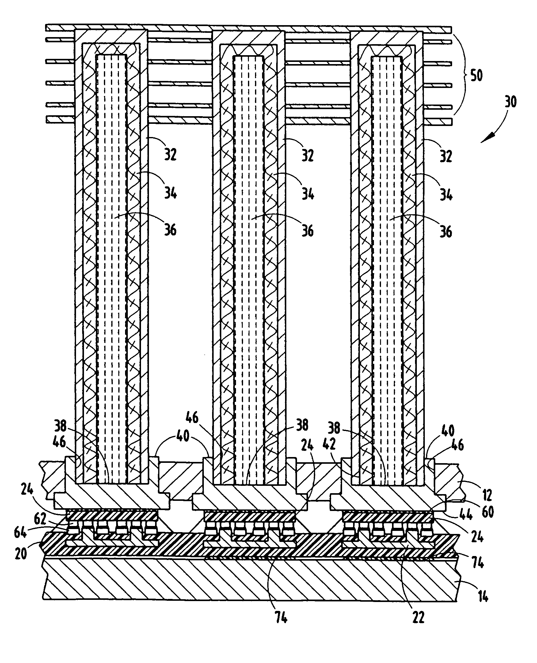
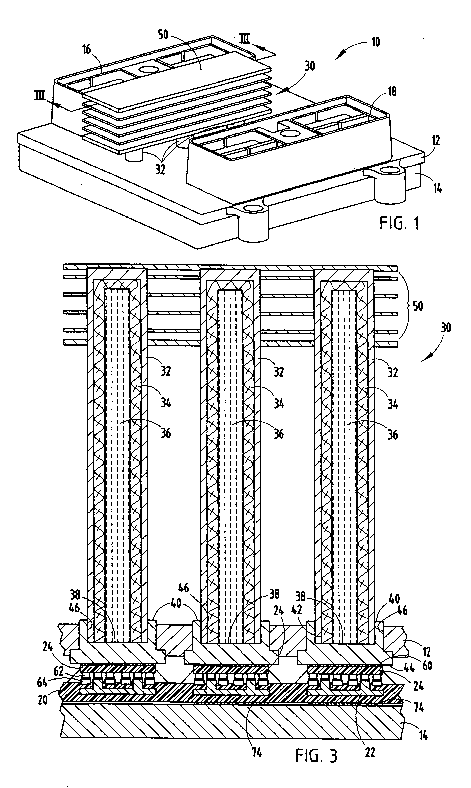
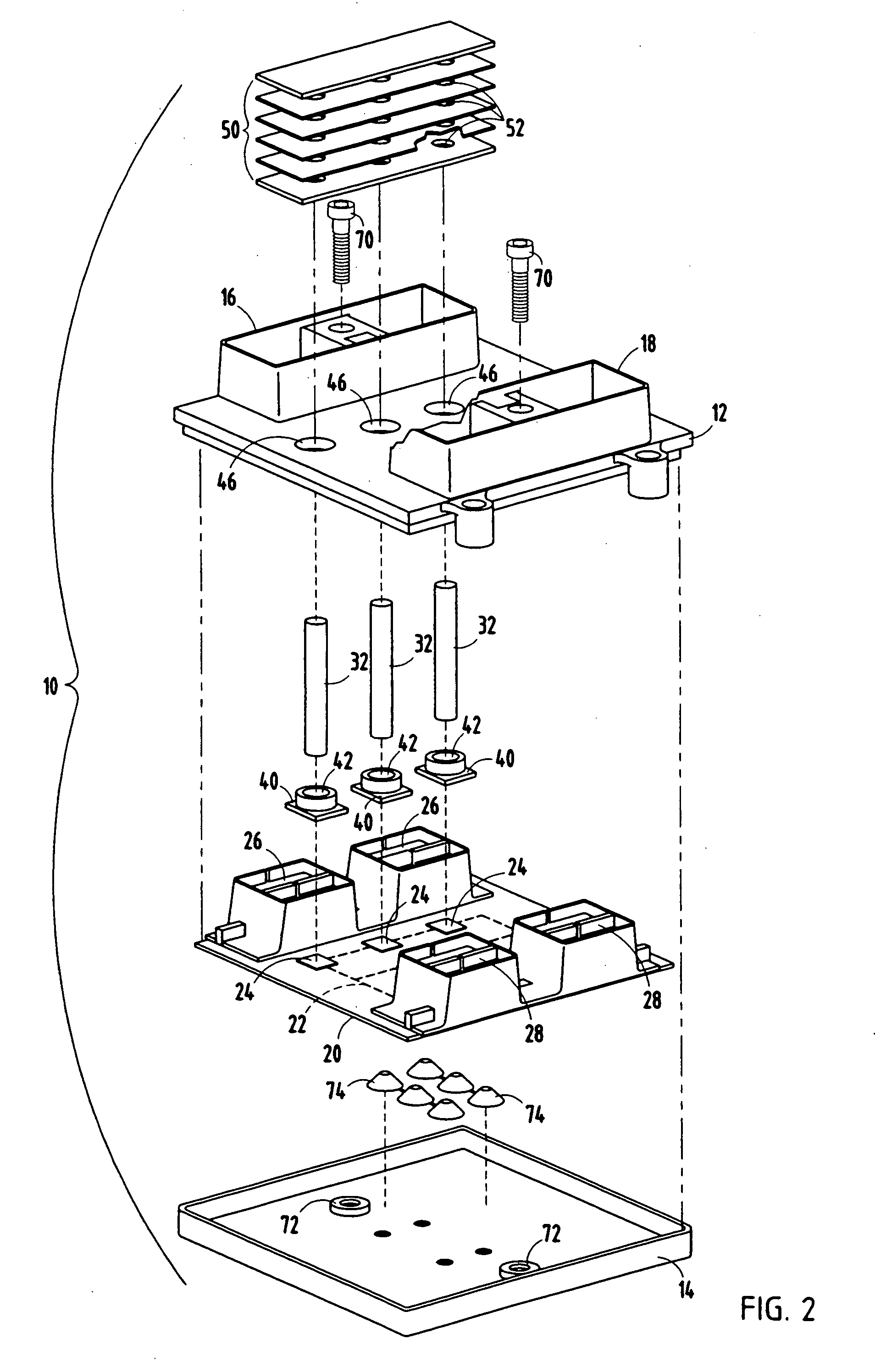
[0016] Referring to FIGS. 1-3, an electronics assembly 10 having heat pipe device 30 is generally illustrated according to one embodiment of the present invention. The heat pipe device 30 according to the present invention is easy to manufacture and provides low cost cooling device for cooling high-power electronics devices. According to one exemplary embodiment, the electronics assembly 10 may include an electronic control module (ECM) containing one or more high-power electronic devices, such as may be employed on electric or hybrid-electric automotive vehicles.

[0017] The electronics assembly 10 generally includes a housing (case) shown generally made-up of an uppercase member 12 and lowercase member 14. Case members 12 and 14 are fastened together via threaded fasteners 70 extending through threaded receivers 72. The case may be made of a thermally conductive material such as metal (e.g., steel or aluminum) to further enhance the heat dissipation from within the electronics asse...


PUM


Abstract

An electronics assembly is provided having a heat pipe device for cooling electronics. The assembly includes a substrate and an electronics package supported on the substrate. The assembly also includes a heat pipe device in thermal communication with an exposed surface of the electronics package. The heat pipe device includes a thermal conductive pipe having an internal volume and an open end. The heat pipe device also includes a thermal conductive end cap positioned to close the open end of the pipe. The end cap has an outer surface for receiving in thermal communication an electronics package. The heat pipe device further includes a cooling fluid disposed in the internal volume of the pipe for transferring thermal energy from the end cap to the outside environment.

Description

TECHNICAL FIELD [0001] The present invention generally relates to cooling of heat generating electronics and, more particularly, relates to a heat pipe device and electronics assembly having a heat pipe device for cooling electronics. BACKGROUND OF THE INVENTION [0002] Power electronics devices typically employ electronics packages that generally contain electrical circuitry for conducting electrical current which, in turn, generates thermal energy (i.e., heat). Automotive high-power electronics, such as those employed in electric and hybrid-electric vehicles, including power and control modules, injector drivers, DC-to-AC converters, and power steering electronics, typically generate a significant amount of thermal energy during operation. Excessive heat build-up may cause reduced performance including electrical circuit failure. Thus, thermal energy must be dissipated and transferred away from the electronics to ensure proper operation of the assembly. Additionally, the power capa...

Claims


Application Information

Patent Timeline
Patent Type & Authority Applications(United States)
IPC IPC(8): H05K7/20
CPCH01L23/427H01L2924/09701H01L2924/0002H01L2924/00
Inventor OMAN, TODD P.
Owner DELPHI TECH IP LTD
Why Eureka
Try Eureka