Color control system for color changing lights

a color control system and control system technology, applied in lighting and heating equipment, process control, instruments, etc., can solve the problems of inability to provide an option, system cannot be programmed to select flashing or steady state color mode, bulky and costly, etc., to simplify the selection process of flashing, reduce the complexity of the system, and cost-effective

Inactive Publication Date: 2007-03-22
GANDHI SAMIR
View PDF15 Cites 88 Cited by
  • Summary
  • Abstract
  • Description
  • Claims
  • Application Information

AI Technical Summary

Benefits of technology

[0016] A further object of the present invention is to reduce the complexity of the system, and to make the system comparatively cost effective, small, intelligent and efficient.
[0017] Yet another object of t

Problems solved by technology

This system is further using stabilizing unit and a digital cycle outputting unit, which makes it limited to only cyclic color changes and does not provide with an option for selecting a single color and the system can not be programmed for selecting flashing or steady state color mode.
In another US Patent publication, number US 2002/0047628, a system is discussed which is more complicated and requires a more complex infrastructure to control and use the system, making it both bulky and costly.
This art is used in larger applications such as in decorating retail, commercial and residential places; thus limiting this system to outdoor environments.
It is not cost-effective in smaller applications.
This patent anticipat

Method used


Image

  • Color control system for color changing lights
  • Color control system for color changing lights
  • Color control system for color changing lights

Examples


Embodiment Construction

[0074] A further understanding of the present invention may be obtained with reference to the following description taken in conjunction with the accompanying drawings. However, the embodiments used for describing the invention are illustrative only and no way limiting scope of the invention. A person skilled in the art will appreciate that many more embodiments of the invention are possible without deviating from the basic concept of the invention any such embodiment will fall under the scope of the invention and is a subject matter of protection.

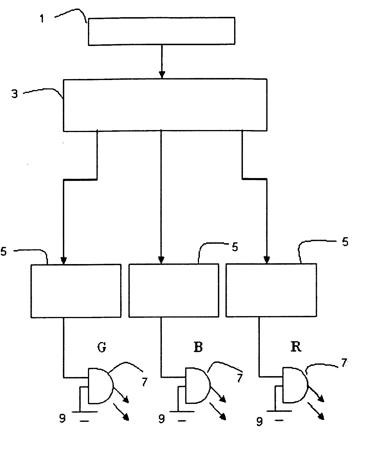
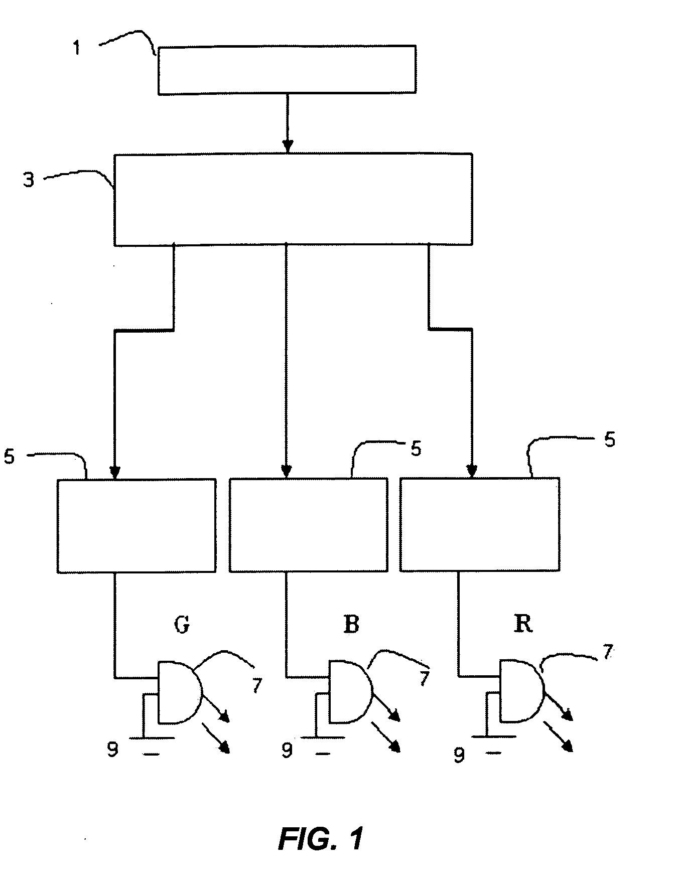
[0075]FIG. 1 shows a basic block diagram of the presented work, the user interface 1 gets the ON / OFF input and sends it to the micro controller 3 which drives the LED Drivers 5. the driver circuit drives single or combination of red, blue and green lighting devices or LED's 7, which are used as the light source, and according to the inputs and micro controllers signals, the LED's emit light.

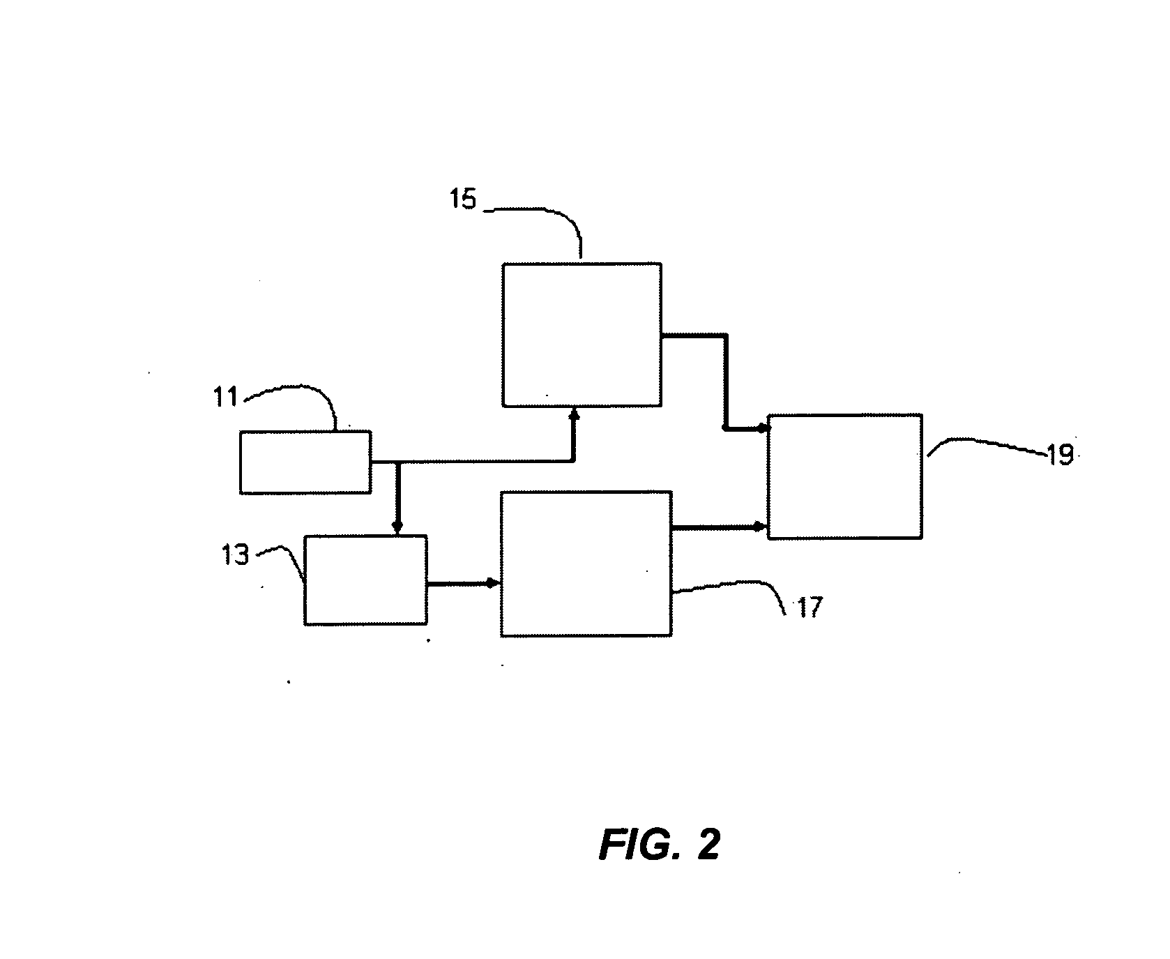
[0076]FIG. 2 shows a simple block diagram of th...


PUM


Abstract

A system and method for color changing lighting comprising a pre-programmed controller along with driver circuit, a single or combination of LEDs and an OFF/ON switch which is used for making selection of mode of operation as well as switching the system ON/OFF. Brightness is changed using pulse width modulation. The LED's are selectively activated by programmed variable pulse to generate desired color mixing effect. The resulting illumination may be controlled by a computer/micro-controller program to provide pre-designed complex patterns of light in virtually any environment.

Description

STATEMENT REGARDING COPYRIGHTED MATERIAL [0001] Portions of the disclosure of this patent document contain material that is subject to copyright protection. The copyright owner has no objection to the facsimile reproduction by anyone of the patent document or the patent disclosure as it appears in the Patent and Trademark Office file or records, but otherwise reserves all copyright rights whatsoever. FIELD OF INVENTION [0002] This invention generally relates to Light Emitting Diodes (LED) lighting systems, and more specifically to a method and apparatus of controlling one or more LED lights in order to provide different colors, and still more precisely to provide different colors, achievable by the system, to the individual LED or combination thereof by digital programming and a time sensitive on-off switching method. BACKGROUND OF THE INVENTION [0003] LEDs are commonly used in lighting applications, and have in many areas superseded conventional lighting, including decorative eleme...

Claims


Application Information

Patent Timeline
IPC IPC(8): F21V9/00
CPCY02B20/341H05B33/0857H05B45/20Y02B20/30
Inventor GANDHI, SAMIR
Owner GANDHI SAMIR
Why Eureka
Try Eureka