Multi-phase converter with improved load step-up transient response

Active Publication Date: 2007-03-22
INFINEON TECH AMERICAS
View PDF3 Cites 18 Cited by
  • Summary
  • Abstract
  • Description
  • Claims
  • Application Information

AI Technical Summary

Benefits of technology

[0011] Accordingly, it is an object of the present invention to provide a multi

Problems solved by technology

Thus there is a delay time until the clock pulse occurs before the converter can respond to the load transient.
This is exacerbated by a situation where a larg

Method used


Image

  • Multi-phase converter with improved load step-up transient response
  • Multi-phase converter with improved load step-up transient response
  • Multi-phase converter with improved load step-up transient response

Examples


Embodiment Construction

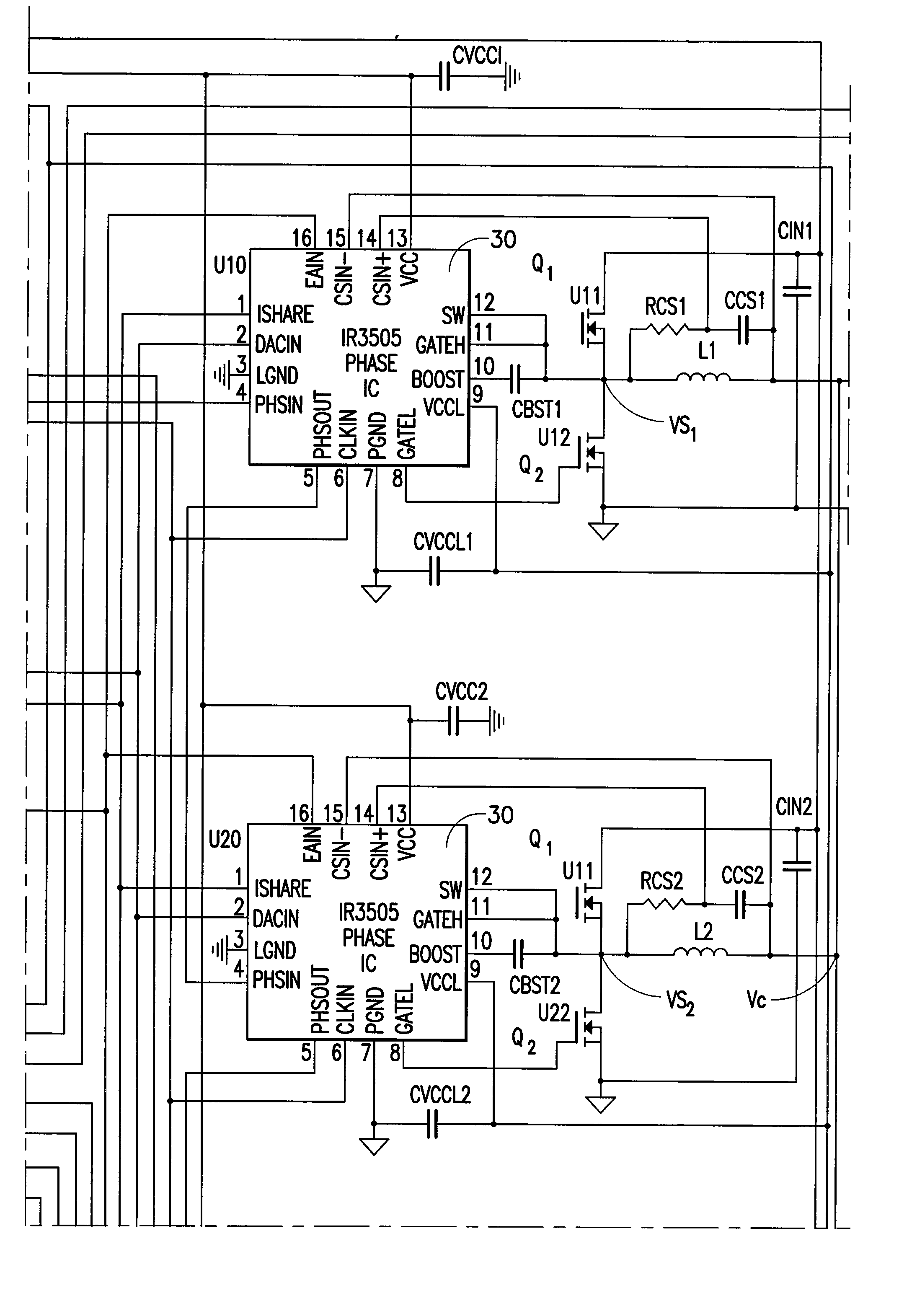
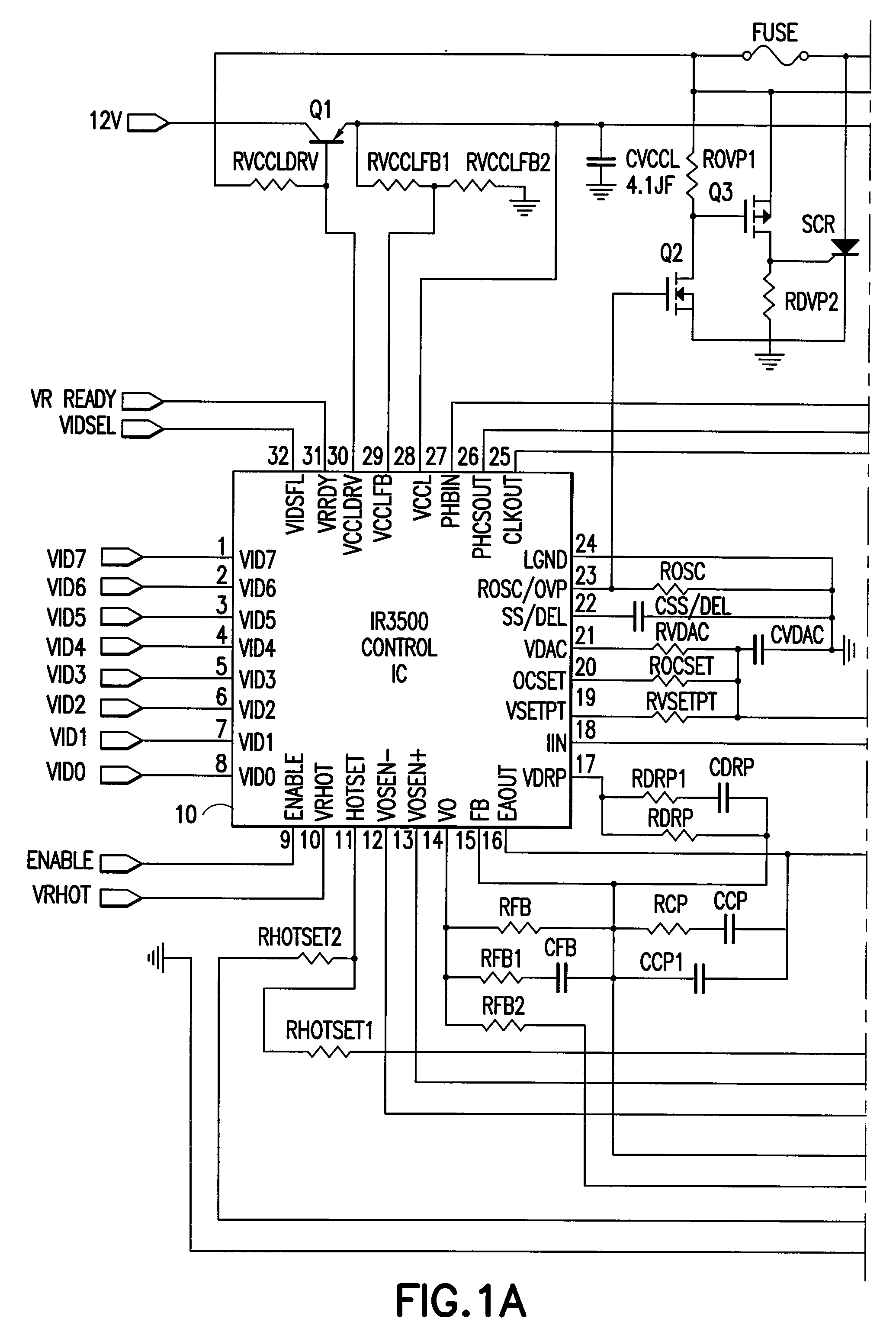
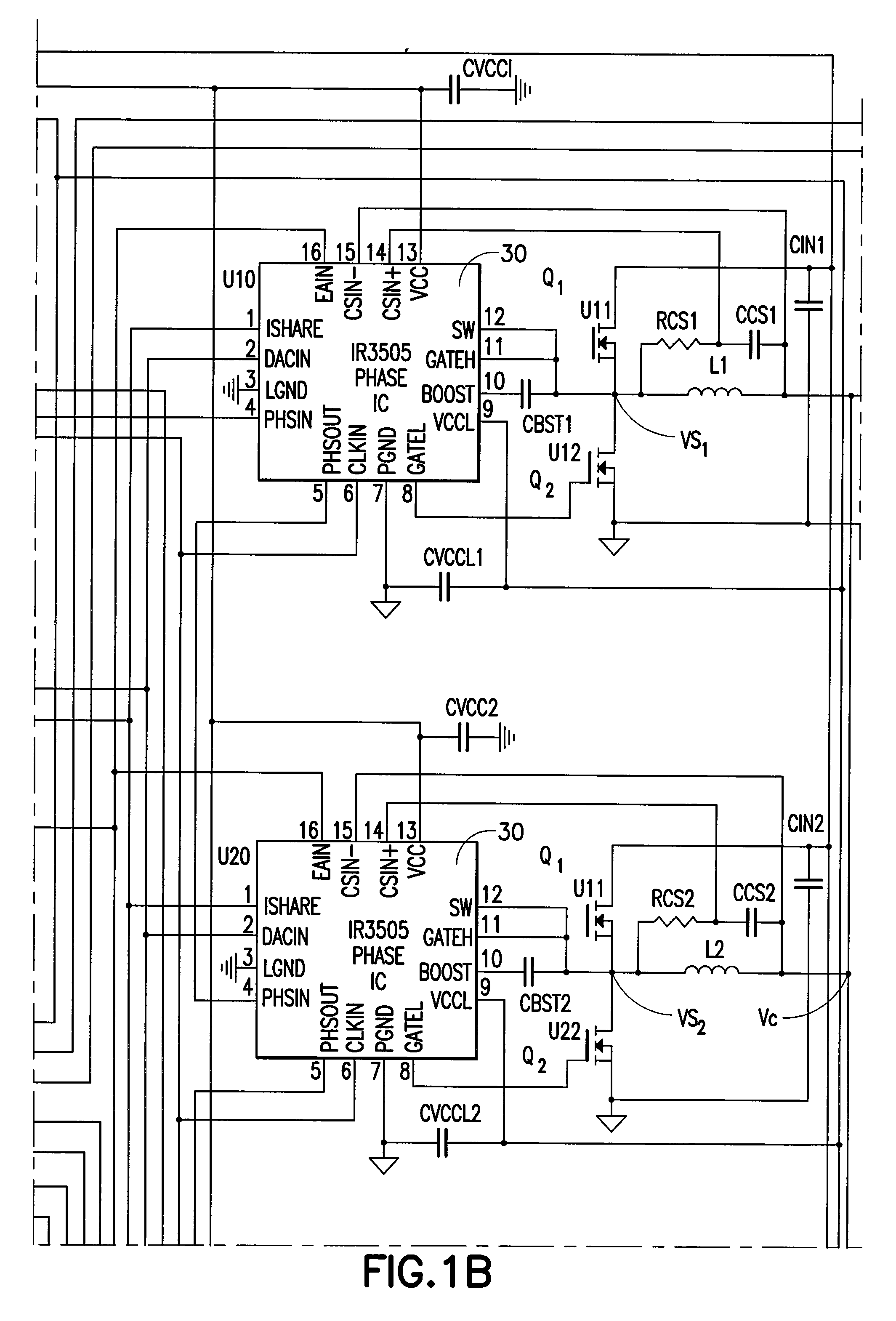
[0023] With reference again to the drawings, FIGS. 1 and 2 show a multi-phase converter to which the invention is applicable. FIG. 2 shows greater details of the circuit of FIG. 1 only showing two phase ICs 30 in detail, which are identical. Each phase IC 30 controls a buck converter comprising two transistors Q1 and Q2 and an output inductor LN. Transistor Q1 is the control switch and transistor Q2 is the synchronous switch. The synchronous switch can be replaced by a diode, as well known to those of skill in the art, although the use of a synchronous switch provides greater efficiency.

[0024] Although FIGS. 1 and 2 show a separate control integrated circuit 10 and phase integrated circuits 30, the circuit can use a single integrated circuit or discrete circuitry or any number of ICs, e.g., all phases in one IC, for example.

[0025] As shown in FIG. 2, the control IC 10 provides a clock signal CLKOUT, as shown in FIG. 3, to each of the phase ICs at the input CLKIN. Dotted lines 15 i...


PUM


Abstract

A multi-phase converter comprising a plurality of switching circuits each providing a switched voltage to an output node of the converter and wherein each switching circuit sequentially provides a switched output voltage to the output node at which an output voltage of the converter is developed; a clock circuit for providing a plurality of out of phase clock signals to the switching circuits to determine when each switching circuit provides the switched voltage to the output node; each switching circuit comprising first and second series connected switches connected across a DC voltage bus; further comprising a first circuit comparing a first signal proportional to a difference between the output voltage of the converter at the output node with a second signal comprising a first reference voltage with a second signal comprising a ramp signal and for producing a pulse width modulated signal to control the on-times of the switches of the connected switching circuit; further comprising a second circuit comparing the first signal proportional to the difference between the output voltage and the first reference voltage to a second reference voltage and if the first signal exceeds the second reference voltage by a prescribed amount, for turning on at least one switching circuit to provide the switched output voltage to the output node prior to occurrence of the clock signal.

Description

CROSS-REFERENCE TO RELATED APPLICATIONS [0001] This application claims the benefit and priority of U.S. Provisional Application Ser. No. 60 / 717,841 filed Sep. 16, 2005 entitled IR3550 / 3505 CHIP, the entire contents of which are incorporated by reference herein.BACKGROUND OF THE INVENTION [0002] The present invention relates to DC to DC converters, and in particular, to multi-phase converters which produce a DC output voltage at the common output of a plurality of coupled switching power supplies, for example, a plurality of buck converters. [0003] Multi-phase converters are known. In a typical multi-phase converter, for example, a multi-phase buck converter, a plurality of buck converters are provided each having their output inductors coupled to the output node. In a typical application, each buck converter is controlled by a control circuit and may be operated such that a control switch of each buck converter switching stage is turned on at a different time than the other phases. ...

Claims


Application Information

Patent Timeline
IPC IPC(8): H02J1/10
CPCH02M3/1584H02M1/14
Inventor SCHUELLEIN, GEORGE
Owner INFINEON TECH AMERICAS
Why Eureka
Try Eureka