
System, method and terminal processing apparatus for optical fiber transmission

Inactive Publication Date: 2007-03-22
HUAWEI TECH CO LTD
View PDF19 Cites 114 Cited by
  • Summary
  • Abstract
  • Description
  • Claims
  • Application Information

AI Technical Summary

Benefits of technology

[0024] The invention provides a system and a method for optical fiber transmission such that optical fiber transmission could be implemented at relatively lower cost in the entire network communication system and the demand for reliable and rapid transmission could be satisfied.

Problems solved by technology

Therefore, these modes can never completely shake off the limitations caused by transmission bandwidth of cables and make full use of the advantages of the optical fiber in bandwidth.
Along with the parallel developments of voice, data and video services, bandwidth limitations of transmission cable have become a big obstacle to the development of telecommunications.
As a result, on one hand, compared with the transmission bandwidth of optical fiber, the bandwidth of less than 155M of these low bandwidth transmission media such as copper cables can guarantee neither enough bandwidth that is needed for data transmission in the entire communication networks nor upgrading and capacity expansion of the communication network; on the other hand, the transmission distance of less than 10 km of these low bandwidth transmission media can also gravely limit the development of communication networks.
However, the problems that need to be solved in applications of optical fiber transmission in an entire network communication system include not only the problem of how to transfer data in the optical fiber, but also that of how to packet the data to be transferred in a user terminal, how to distribute the data when the user terminal receives a data packet that contains different types of data, how to switch the data after the data have been transferred through the devices at the network side and etc.
An SDH / WDM transmission network can provide carrier-class services with excellent QoS (Quality of Service) and security characteristics while the complicated layered network architecture of its switching portion increases the cost of network construction and maintenance.
So the network architecture is very complex.
In one word, layered network architecture and separate networking of the three major services make the overall networking cost and overall maintenance cost of existing communication networks remain high while problems in QoS of IP networks lowers the transmission quality of real-time services including video phone, video conference, and etc.
Therefore, applications of optical fiber transmission technology at present have the following problems:
1, the complicated layered network architecture makes the overall cost of network construction and maintenance remain high;
2, the separate construction of the layer of voice, data and video service networks in network communications brings about higher overall cost of network construction and maintenance, resulting in wastes caused by redundant network construction;
3, the relatively low bandwidth transmission media existing in the entire communication network, compared with the transmission bandwidth of optical fiber, can not meet the bandwidth requirement of subscribers, making it impossible to guarantee the QoS in network communications, for instance, there are relatively serious time delay and jittering in videophone and videoconference services;
4, the commonly used ring structure in network communications has relative poor protecting effects on data transmission;
5, neither application for bandwidth resources based on each call nor allocation of bandwidth resources on demand is supported in existing network communications, making it impossible to satisfy the diversified needs of users;
6, the electric magnetic radiation generated from copper transmission cables commonly used in communication networks damages the surrounding environment while surrounding electric magnetic radiation can also interfere with the signals transferred through copper cables.

Method used


Image

  • System, method and terminal processing apparatus for optical fiber transmission
  • System, method and terminal processing apparatus for optical fiber transmission
  • System, method and terminal processing apparatus for optical fiber transmission

Examples


Embodiment Construction

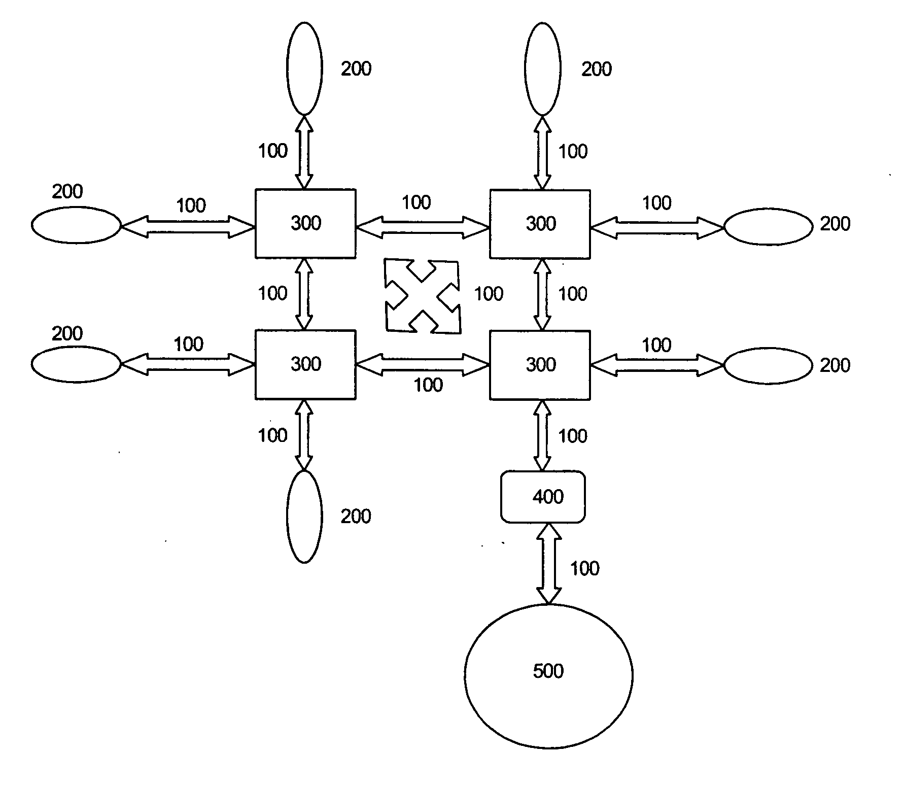
[0063] The optical fiber transmission system in accordance with this embodiment of invention at least comprises three parts, a switch unit, an optical transmission unit and a terminal processing unit. Besides, under the circumstances of several types of communication networks coexisting, such as the case when an optical fiber transmission system needs to interconnect with traditional telephone network and television network, it is necessary to have a gateway unit that is used for implementing protocol conversion between the optical fiber transmission system and other types of networks, and the physical entity of the gateway can be integrated into the switch unit. FIG. 2 shows the architecture of the system according to the embodiment of present invention, where terminal processing unit 200 connects with switch unit 300 through optical fiber transmission unit 100 while different switch units 300 are interconnected with each other via optical fiber transmission unit 100 such that the ...


PUM


Abstract

Disclosed by the present invention is a system and method for optical fiber transmission. The switching portion of the present invention adopts the single-layered integrated switching technology so as to ensure a relatively simple and easy maintenance compared with the switching in a traditional communication network where said switching is made in the service network layer and the bearer network layer, respectively. Moreover, the present invention implements data transmission via optical fiber throughout the entire telecommunication system such that demands for bandwidth resources are satisfied during the whole data transmission process and the QoS (Quality of Service) of different services as well as rapid and un-blocking switching of the services are ensured in the telecommunication system. Therefore, the present invention can implement on-demand allocation of bandwidth resources, enhancing the flexibility in network resource management while a subscriber can apply for bandwidth resources based on its demand, which satisfies the individual needs of the user.

Description

FIELD OF THE TECHNOLOGY [0001] The present invention generally relates to network communication technology, and more particularly, to a system, terminal processing apparatus and method for optical fiber transmission. BACKGROUND OF THE INVENTION [0002] At present, optical fiber transmission has been widely used in telecommunication system. In access layer, the commonly used modes are “optical fiber+category 5 cabling LAN (Local Area Network)”, “optical fiber+xDSL (x Digital Subscriber Line)” or “optical fiber+Coaxial-Cable”, in which all User Equipments (UEs) connect with optical fiber through cables rather than directly. Therefore, these modes can never completely shake off the limitations caused by transmission bandwidth of cables and make full use of the advantages of the optical fiber in bandwidth. Along with the parallel developments of voice, data and video services, bandwidth limitations of transmission cable have become a big obstacle to the development of telecommunications....

Claims


Application Information

Patent Timeline
IPC IPC(8): G02B6/36H04B10/20H04L12/28H04L12/46H04L12/56
CPCH04L12/2861H04L12/2885H04L2012/5612H04L12/5602H04L2012/5605H04L12/4604H04B10/25H04B10/27H04B10/00
Inventor JIANG, SHUMIAO
Owner HUAWEI TECH CO LTD
Learn More