
Symmetrical, bi-electrode supported solid oxide fuel cell

a solid oxide fuel cell, bi-electrode supported technology, applied in the field of fuel cells, can solve the problems of not providing cell support, complete cell based on moon's technology has not been currently fabricated or tested,

Active Publication Date: 2007-03-22
U S GOVERNMENT AS REPRESENTED BY THE ADMINSTRATOR OF NAT AERONAUTICS & SPACE ADMINISTATION
View PDF19 Cites 57 Cited by
  • Summary
  • Abstract
  • Description
  • Claims
  • Application Information

AI Technical Summary

Benefits of technology

[0013] The invention is a symmetrical bi-electrode supported solid oxide fuel cell comprising a monolithic framework including a first porous electrode scaffold, a second porous electrode scaffold and a thin electrolyte layer that is monolithically disposed between the first and the second electrode scaffolds. The outermost exposed surfaces of each of the first and second porous electrode scaffolds each has a thin electrically conductive ceramic coating deposited on it having essentially the same coefficient of thermal expansion as the first and second porous electrode scaffolds and the thin electrolyte layer and both thin electrically conductive coatings are made of doped LaCrO3 and each has a thickness in the range of about 2 um to about 200 um, and a preferred thickness in the range of about 5 um to about 25 um. Two opposing edges of the first porous electrode scaffold each has a ceramic sealant placed over it, and two opposing edges of the second porous electrode scaffold each has a ceramic sealant placed over it, and each ceramic sealant has essentially the same coefficient of thermal expansion as the first and second porous electrode scaffolds, the thin electrolyte layer and the thin electrically conductive ceramic coatings. The monolithic framework is sintered. The first porous electrode scaffold and the second porous electrode scaffold each has a thickness in the range of about 100 um to about 1,500 um, and a preferred thickness in the range about 300 um to about 750 um. The thin electrolyte layer are made of essentially on

Problems solved by technology

The thin porous region is fabricated using traditional ceramic processing techniques, it does not have graded porosity, and it does not provide support for the cell.
A complete cell based on Moon's technology has not been currently fabricated or tested.

Method used


Image

  • Symmetrical, bi-electrode supported solid oxide fuel cell
  • Symmetrical, bi-electrode supported solid oxide fuel cell
  • Symmetrical, bi-electrode supported solid oxide fuel cell

Examples


Embodiment Construction

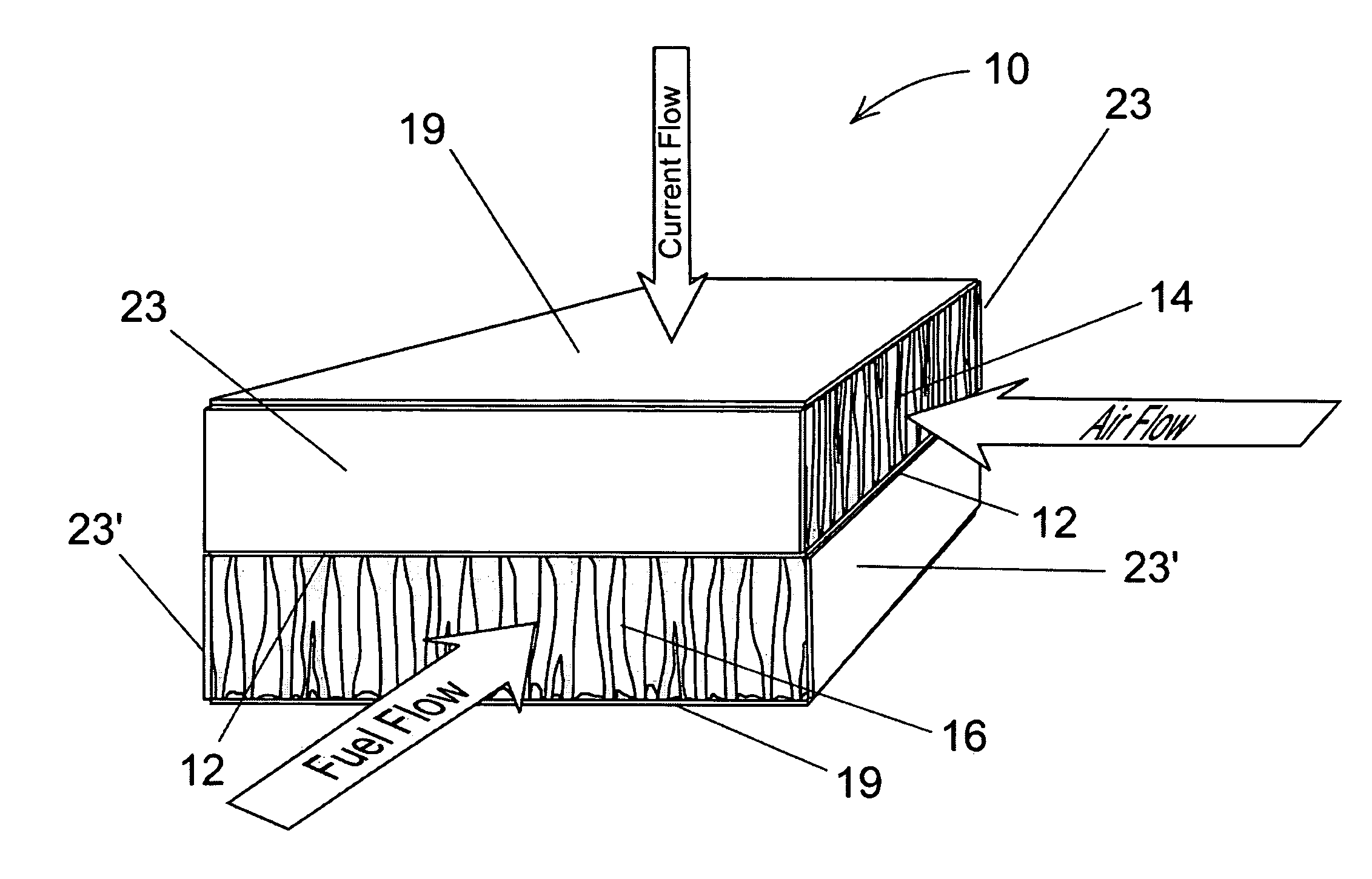
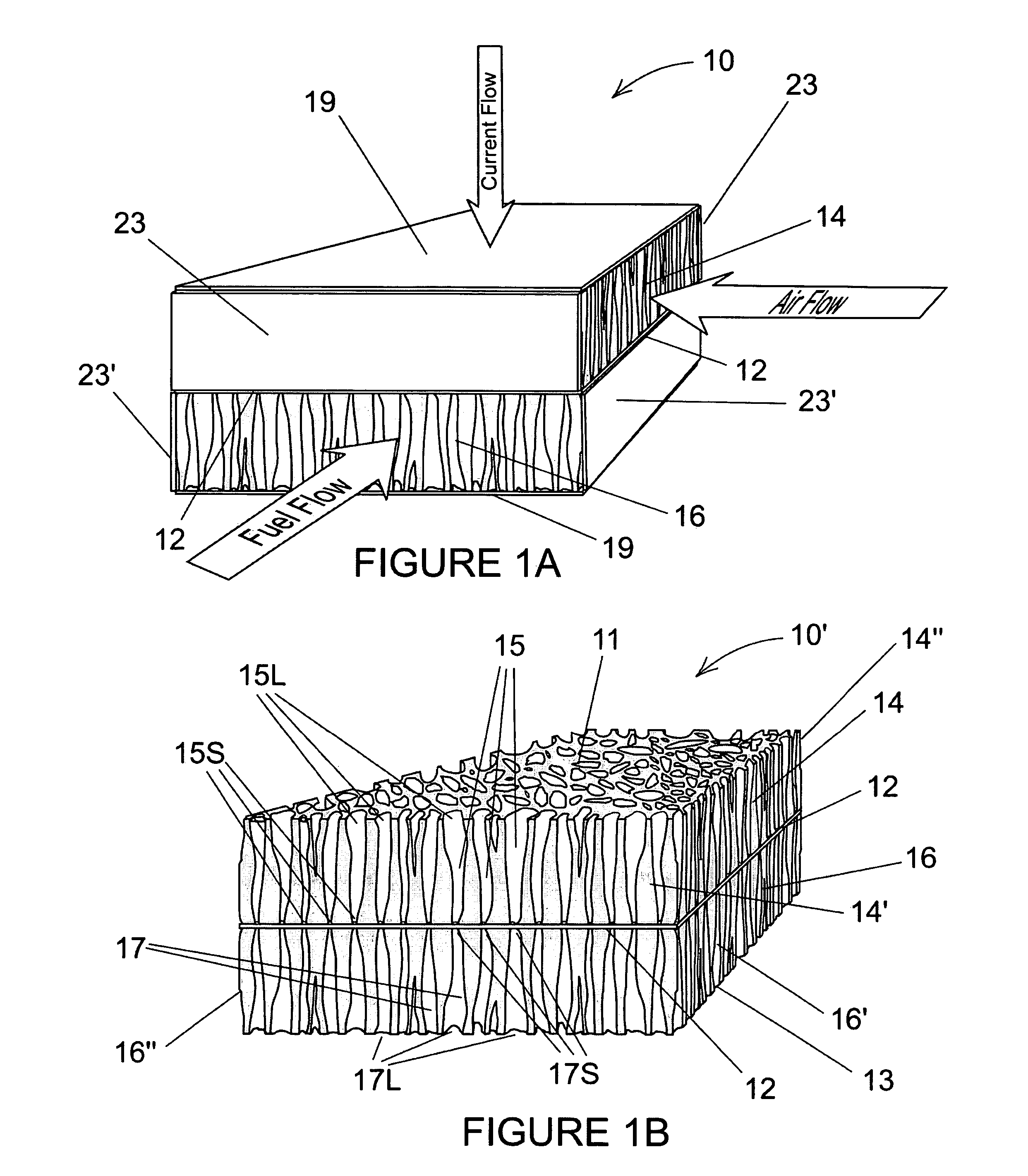
[0037] The present invention addresses the aforementioned difficulties of solid oxide fuel cell (SOFC) fabrication and reliability and weight associated with the anode supported cell design (ASC) and the metal interconnects used to connect separate cells a fuel cell stack. More specifically, the present invention is a symmetrical, bi-electrode supported fuel cell (BSC), shown in the oblique schematic view in FIG. 1A, comprising a monolithic framework 10 including as main operational elements a first electrode scaffold 14, a second electrode scaffold 16, and a thin electrolyte layer 12 that is monolithically disposed between the first and the second electrode scaffolds. The thin electrolyte layer 12 has a thickness of between 2 um and 200 um, and most preferably between 5 um and 25 um. The two outermost exposed surfaces of the first electrode scaffold 14 and the second electrode scaffold 16 each also has a thin electrically conductive ceramic coating 19 deposited on it. The coatings ...


PUM

PropertyMeasurementUnit
Temperatureaaaaaaaaaa
Lengthaaaaaaaaaa
Lengthaaaaaaaaaa

Abstract

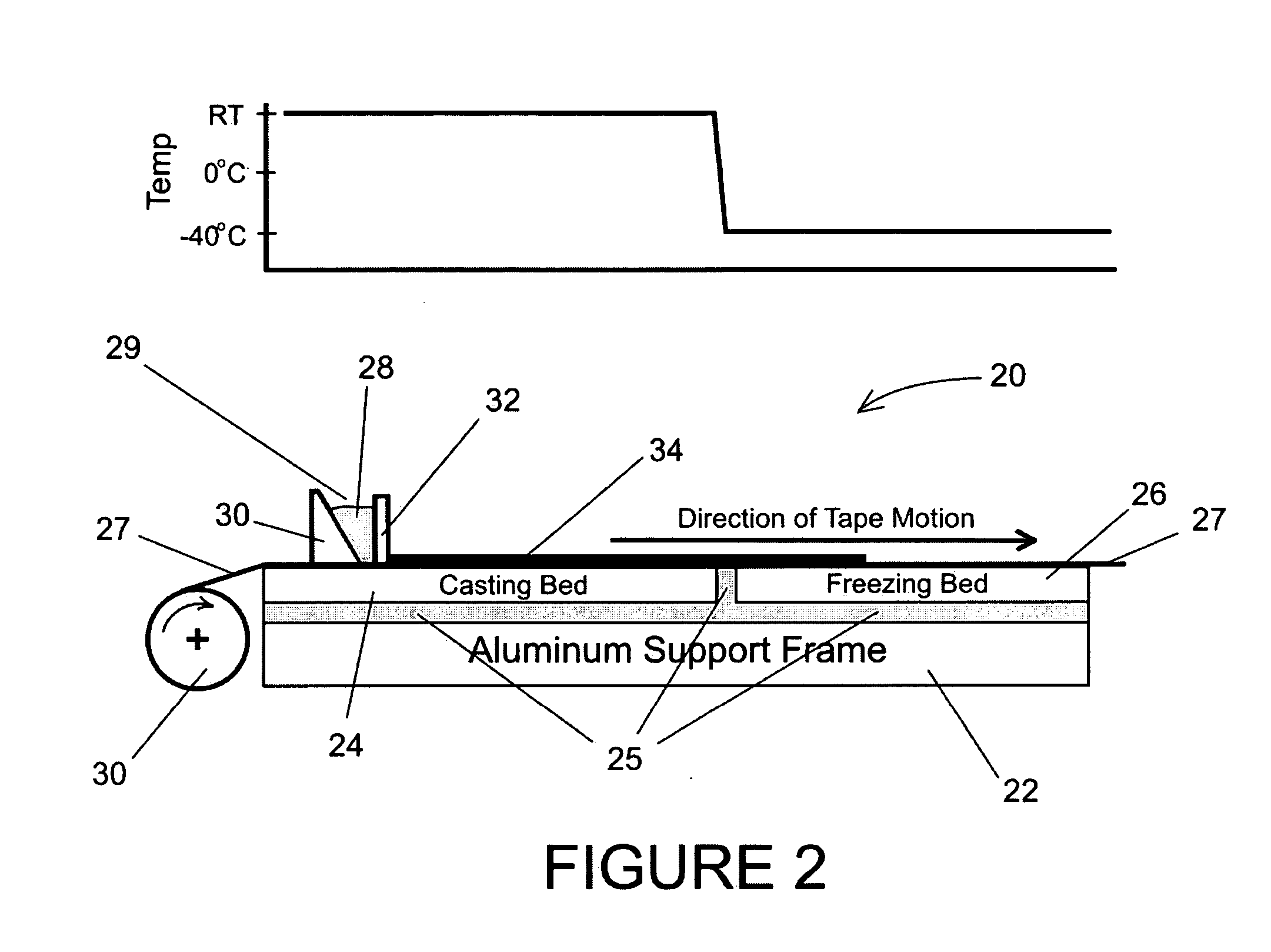
The present invention is a symmetrical bi-electrode supported solid oxide fuel cell comprising a sintered monolithic framework having graded pore electrode scaffolds that, upon treatment with metal solutions and heat subsequent to sintering, acquire respective anodic and cathodic catalytic activity. The invention is also a method for making such a solid oxide fuel cell. The graded pore structure of the graded pore electrode scaffolds in achieved by a novel freeze casting for YSZ tape.

Description

STATEMENT REGARDING FEDERALLY SPONSORED RESEARCH OR DEVELOPMENT [0001] The invention described herein was made by an employee of the United States Government and may be manufactured and used by or for the Government for Government purposes without the payment of any royalties thereon or therefore. CROSS-REFERENCE TO RELATED APPLICATIONS [0002] The present application relates to co-pending U.S. patent application Ser. No. ______ (Attorney Docket No. LEW-17,634-1 filed concurrently herewith) entitled MONOLITHIC SOLID OXIDE FUEL CELL STACK WITH SYMMETRICAL, BI-ELECTRODE SUPPORTED CELLS. FIELD OF THE INVENTION [0003] The present invention relates generally to fuel cells and more particularly to high power density solid-oxide fuel cells and the fabrication thereof. BACKGROUND [0004] Fuel cells consist essentially of two electrodes that are in contact with an electrolyte. For example, the electrolyte can be a water solution of an acid, such as phosphoric acid, or, as explained below, it c...

Claims


Application Information

Patent Timeline
IPC IPC(8): H01M8/02H01M8/12H01M4/86B05D5/12H01M4/88A01J21/00
CPCC04B35/486C04B35/62655C04B2235/5436C04B2235/5445C04B2235/6025H01M4/8657Y02E60/525H01M8/1213H01M8/1253H01M8/2435H01M2008/1293H01M2300/0077Y02E60/521H01M8/028Y02E60/50Y02P70/50
Inventor CABLE, THOMAS L.SOFIE, STEPHEN W.
Owner U S GOVERNMENT AS REPRESENTED BY THE ADMINSTRATOR OF NAT AERONAUTICS & SPACE ADMINISTATION
Learn More