
Electrokinetic Infusion Pump System

Inactive Publication Date: 2007-03-22
LIFESCAN INC
View PDF98 Cites 211 Cited by
  • Summary
  • Abstract
  • Description
  • Claims
  • Application Information

AI Technical Summary

Benefits of technology

[0009] The present invention generally provides methods and devices for delivering an infusion liquid using an electrokinetic infusion pump. In one embodiment, an electrokinetic infusion pump is provided which includes an infusion housing having an infusion reservoir. The infusion reservoir has an infusion outlet and is capable of containing an infusion liquid. A plunger is movably coupled to the infusion housing and is adapted to be manually displaced relative to the infusion housing to load the infusion reservoir with infusion liquid. A movable partition can be disposed within the infusion housing and has a first surface in communication with an electrokinetic solution and a second surface, isolated from the first surface, in communication with the infusion reservoir. The electrokinetic infusion pump further includes an electrokinetic engine integrated within the plunger and adapted to selectively apply electric potential across an electrokinetic porous media to cause the electrokinetic solution within the electrokinetic engine to displace the movable partition to effect delivery of at least a portion of the infusion liquid through the infusion outlet.
[0012] The application of electric potential across the porous media can be effective to cause electrokinetic solution in the fixed supply chamber to flow through the porous media, into the fixed receiving chamber, through the inner channel of the forward piston and into the adjustable receiving chamber, causing a distally directed force to be placed on the displacement piston. This results in distal movement of the movable partition which will effect dispensing of at least a portion of the infusion liquid through the infusion outlet.
[0014] The electrokinetic infusion pump can also include a latch disposed on a portion of the plunger. The latch is selectively movable between a latched condition in which it is coupled to the displacement piston to allow movement of the displacement piston and the movable partition with movement of the plunger, and an unlatched condition in which it is uncoupled from the displacement piston to permit movement of the displacement piston and the movable partition independent of the plunger. The latched condition allows for loading of the infusion liquid into the infusion reservoir, and the unlatched condition allows for delivery of at least a portion of the infusion liquid through the infusion outlet when an electric potential is applied across the porous media to cause the electrokinetic solution within the electrokinetic engine to displace the movable partition.
[0015] In one embodiment of the invention, the plunger can include a knob disposed on a proximal end thereof. The knob is adapted for grasping by a user to enable rotational and longitudinal movement of the plunger. In one exemplary embodiment, a surface of the outer plunger housing includes an axial groove formed along at least a portion of the length thereof and a perimeter groove extending transversely from a distal portion of the axial groove. The perimeter groove is angled towards a proximal end of the outer plunger housing. The infusion housing can include a surface feature slidably disposed within the axial and perimeter grooves of the outer plunger housing. The knob disposed on the plunger is adapted to move the plunger proximally to fill the infusion reservoir with infusion liquid, and the plunger is adapted to move proximally until the surface feature reaches the distal end of the axial groove. The knob is able to be rotated to cause the surface feature to travel along the perimeter groove to allow at least a portion of the infusion liquid to be delivered through the infusion outlet to prime the infusion pump. A first locking feature provided on the infusion housing can irreversibly engage a second locking features provided on the plunger to lock the plunger to the infusion housing.
[0018] In one embodiment, the electrokinetic porous media can separate a collapsible supply chamber containing an electrokinetic solution and an expandable receiving chamber within the electrokinetic engine such that electrokinetic solution is able to flow from the supply chamber through the porous media and into the expandable receiving chamber when a voltage is applied to the electrokinetic solution infusion module. The transfer of the electrokinetic solution from the collapsible supply chamber can be effective to expand the expandable receiving chamber such that the expandable receiving chamber applies a compressive force to the deformable infusion reservoir to effect delivery of the infusion liquid.

Problems solved by technology

However, with most conventional diagnostic and therapeutic medical systems, precise movement of large and small aqueous volumes of drugs and other bio-fluids is difficult to achieve.
This difficulty arises because conventional systems employ mechanical components to effect fluid transport and delivery.
Modification of such systems, to enable highly precise movement of small and large aqueous volumes of a solution containing biomaterials, would be impractical, as the complexity of such systems would make their manufacture expensive, time consuming and labor intensive.
Further, such modification is likely to result in systems that are too large for many intended applications.
While electro-osmosis has found widespread and wide ranging applications in chemical analysis (e.g., high-speed liquid chromatography and other chemical separation procedures), its medical applications, such as for drug delivery and analyte sampling, have been limited, despite its advantages over conventional, mechanical approaches.

Method used


Image

  • Electrokinetic Infusion Pump System
  • Electrokinetic Infusion Pump System
  • Electrokinetic Infusion Pump System

Examples


example

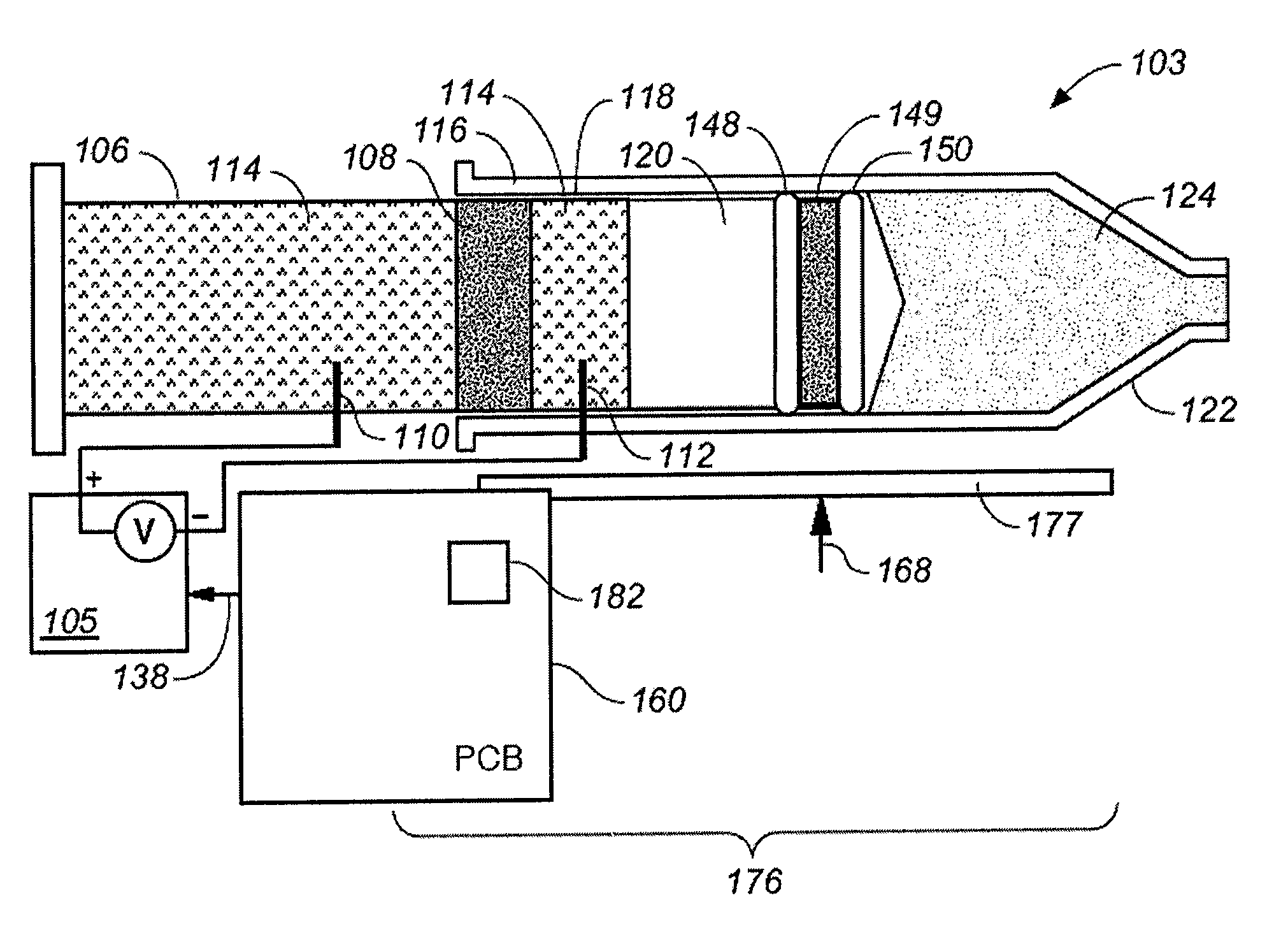
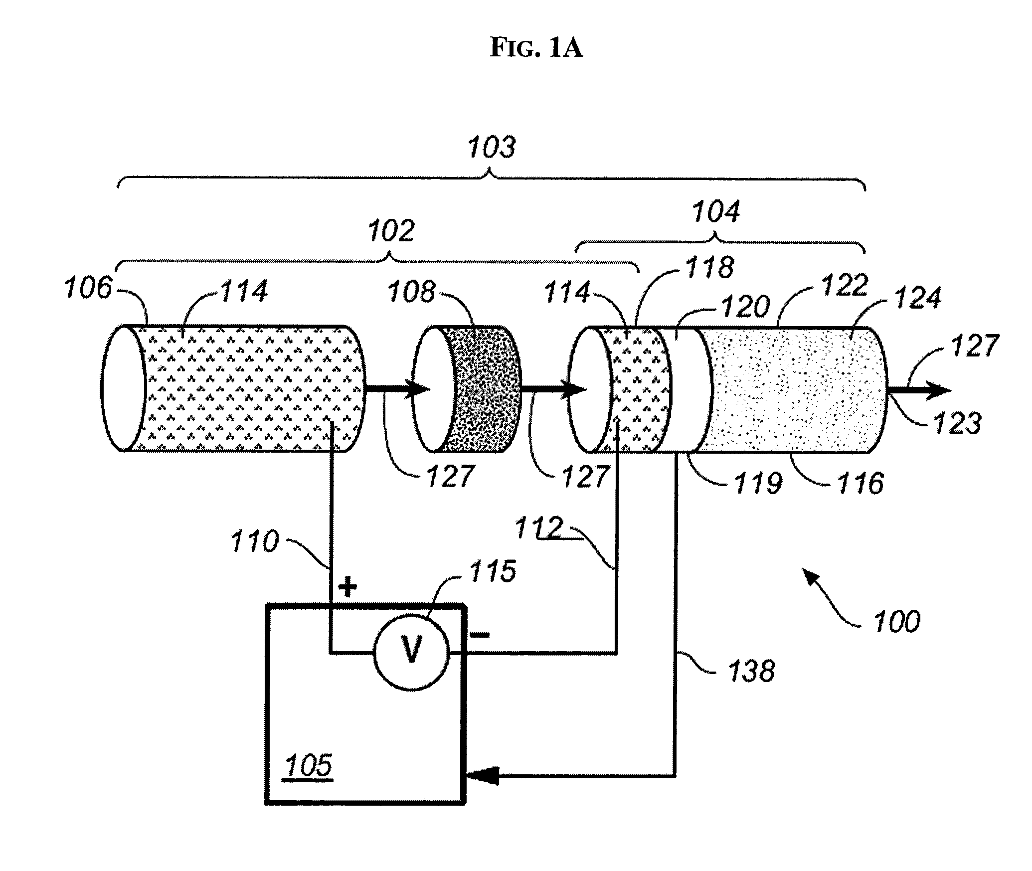
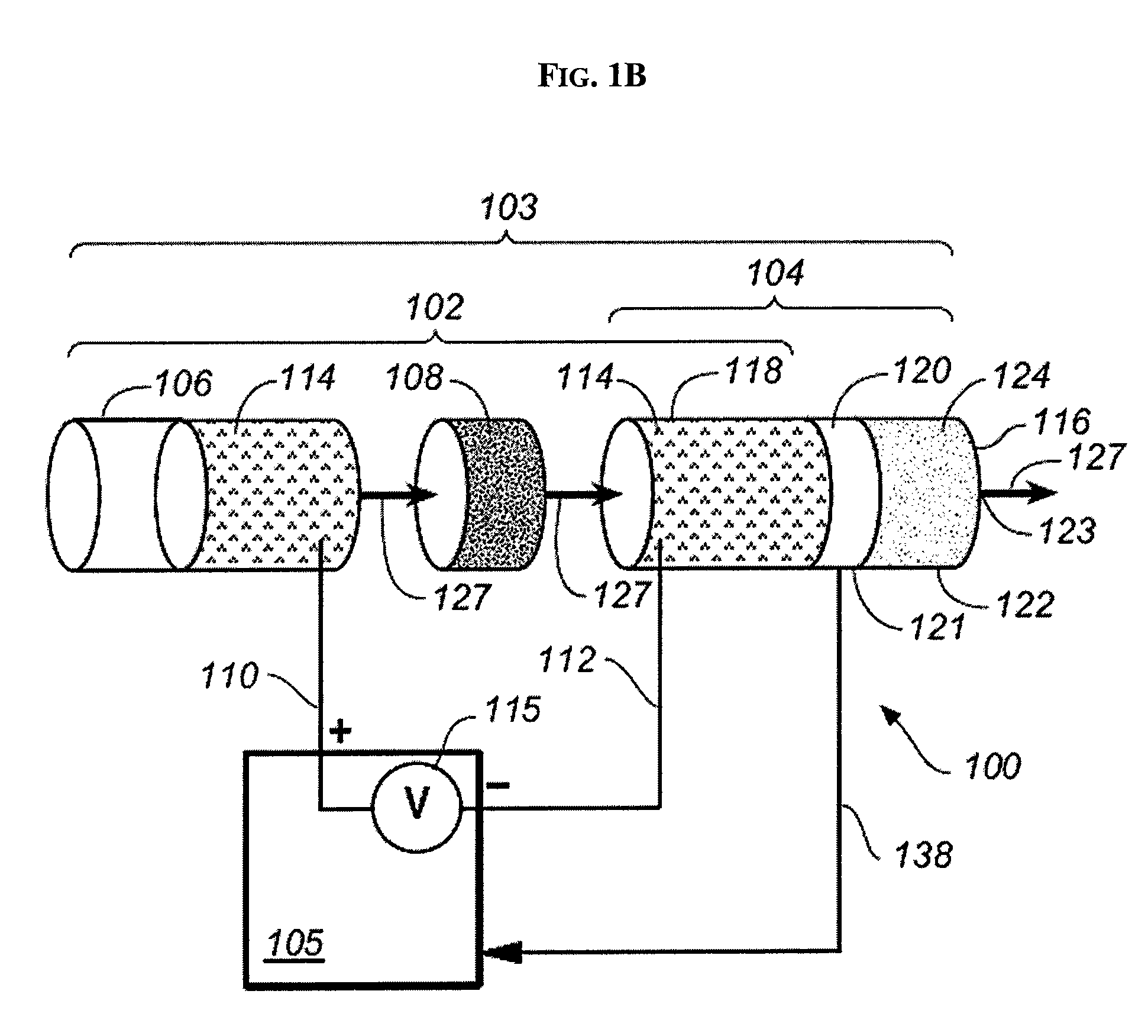
[0137] As mentioned previously, when designing an electrokinetic infusion pump with closed loop control 1100, the infusion module 1104 and the electrokinetic engine 1102 can be integrated, as illustrated in FIGS. 33, 35, 36, 37, and 38, or they can be separate components connected with tubing, as illustrated in FIG. 39. In FIG. 39, electrokinetic infusion pump with closed loop control 1100 includes infusion module 1104 and electrokinetic engine 1102, connected by connection tubing 1244. Infusion module 1104 includes moveable partition 1120 and infusion reservoir outlet 1123. The moveable partition 1120 includes moveable permanent magnet 1149. Further details regarding electrokinetic engine 1102, including materials, designs, and methods of manufacturing, suitable for use in electrokinetic infusion pump with closed loop control 1100 are included in U.S. patent application Ser. No. 10 / 322,083, previously incorporated by reference. Using electrokinetic infusion pump with closed loop co...


PUM


Abstract

Various methods and devices are provided for delivering an infusion liquid using an electrokinetic infusion pump. The electrokinetic infusion pump can generally include an infusion housing having an infusion reservoir. The infusion reservoir has an infusion outlet and is capable of containing an infusion liquid. A plunger is movably coupled to the infusion housing and is adapted to be manually displaced relative to the infusion housing to load the infusion reservoir with infusion liquid. A movable partition can be disposed within the infusion housing and has a first surface in communication with an electrokinetic solution and a second surface, isolated from the first surface, in communication with the infusion reservoir. The electrokinetic infusion pump can further include an electrokinetic engine integrated within the plunger and adapted to selectively deliver electric potential across an electrokinetic porous media to cause the electrokinetic solution within the electrokinetic engine to displace the movable partition to effect delivery of at least a portion of the infusion liquid through the infusion outlet.

Description

CROSS-REFERENCE TO RELATED APPLICATIONS [0001] This Application claims the benefit of priority to U.S. Provisional Application Serial No. 60 / 718,400, filed Sep. 19, 2005 entitled “Electrokinetic Pump Integrated within a Plunger of a Syringe Assembly;” No. 60 / 718,398, filed Sep. 19, 2005 entitled “Reduced Size Electrokinetic Pump Using an Indirect Pumping mechanism with Hydraulic Assembly;” No. 60 / 718,399, filed Sep. 19, 2005 entitled “Electrokinetic Syringe Pump with Manual Prime Capacity and Method of Use;” No. 60 / 718,364, filed Sep. 19, 2005 entitled “Syringe-Type Electrokinetic Infusion Pump for Delivery of Therapeutic Agents;” No. 60 / 718,578, filed Sep. 19, 2005 entitled “Syringe-Type Electrokinetic Infusion Pump and Method of Use;” No. 60 / 718,289, filed Sep. 19, 2005 entitled “Manual Prime Capability of an Electrokinetic Syringe Pump and Method of Use;” No. 60 / 718,572, filed Sep. 19, 2005 entitled “Electrokinetic Infusion Pump with Detachable Controller and Method of Use;” No. ...

Claims


Application Information

Patent Timeline
IPC IPC(8): A61M1/00
CPCA61M5/16831A61M5/172A61M2005/14513A61M5/1452A61M2205/3389A61M5/14244A61M5/14248A61M2205/3317
Inventor KRULEVITCH, PETERBENETT, WILLIAMROBERTS, NEIL E.BOHM, SEBASTIANSIEH, ZARA
Owner LIFESCAN INC
Learn More