Uni-index variable angle phased array probe

a phased array, variable angle technology, applied in the field of ultrasonic probes, can solve the problems of slow analysis, delay in signal timing, and difficult operation of signal processing equipment, so as to achieve accurate scan of workpieces, accurate scan, and faster and more reliably

Inactive Publication Date: 2007-03-29
GENERAL ELECTRIC CO
View PDF14 Cites 21 Cited by
  • Summary
  • Abstract
  • Description
  • Claims
  • Application Information

AI Technical Summary

Benefits of technology

[0016] Another advantage of the present invention is that the calculations can be performed more quickly and more reliably. Additionally, the ultrasonic testing of a volume of the material can be performed without moving the probe, but by simply implementing a program that fires preselected elements of the array in a prearranged sequence and in a prearranged timing pattern so as to scan the volume. Rather than having to move the probe across the entire surface of the workpiece, a thorough scan of the workpiece can be accomplished by simply moving the probe linearly, along a single dimension, rather than in a planar fashion, along a surface of the test piece.
[0017] Still another advantage of the present invention is that an accurate scan of the workpiece can be achieved when the workpiece is a complex shape. With such work pieces, an accurate scan can be achieved when only one surface is suitable for interfacing with the probe. Indeed, depending upon the configuration of the workpiece, an accurate scan may be achieved when only a portion of a surface is suitable. Of course, other factors will enter into such testing, such as filtering back reflections and reflections from indications, but full volumetric testing using ultrasonics which previously were precluded by the complex shape of the workpiece may now be possible.

Problems solved by technology

The signal processing equipment, including the apparatus for generating electrical signals and the signal analysis equipment, including associated software and algorithms, can be quite complex.
Because of the shape of the delay body, sound generated or received by the transducer or transducers in the array pass through unequal amounts of material in the delay body, resulting in a timing delay for the signal.
While this time delay can be accounted for in the analysis, it leads to complications that slow the analysis and which add to the potential for errors.

Method used


Image

  • Uni-index variable angle phased array probe
  • Uni-index variable angle phased array probe
  • Uni-index variable angle phased array probe

Examples


Embodiment Construction

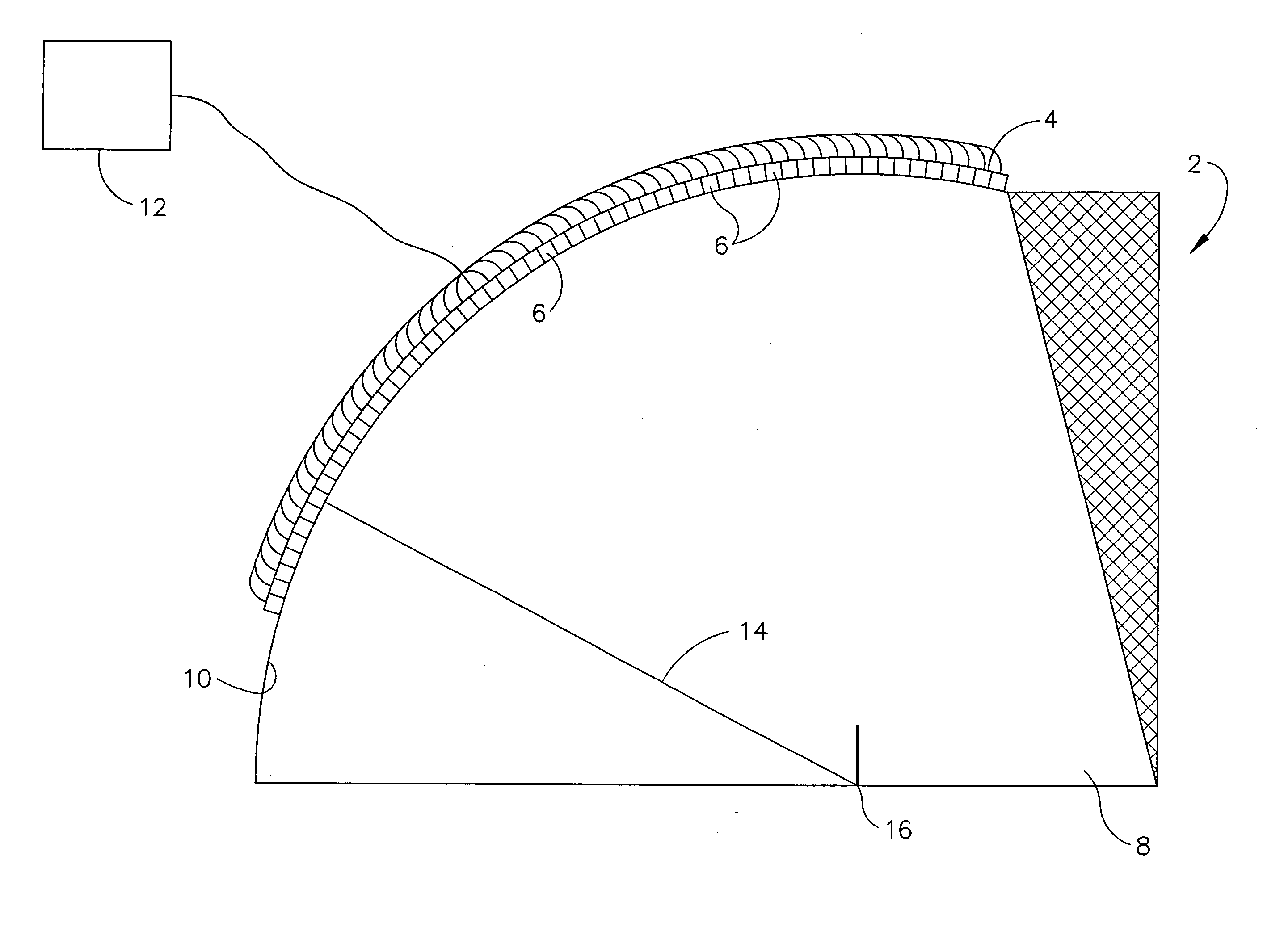
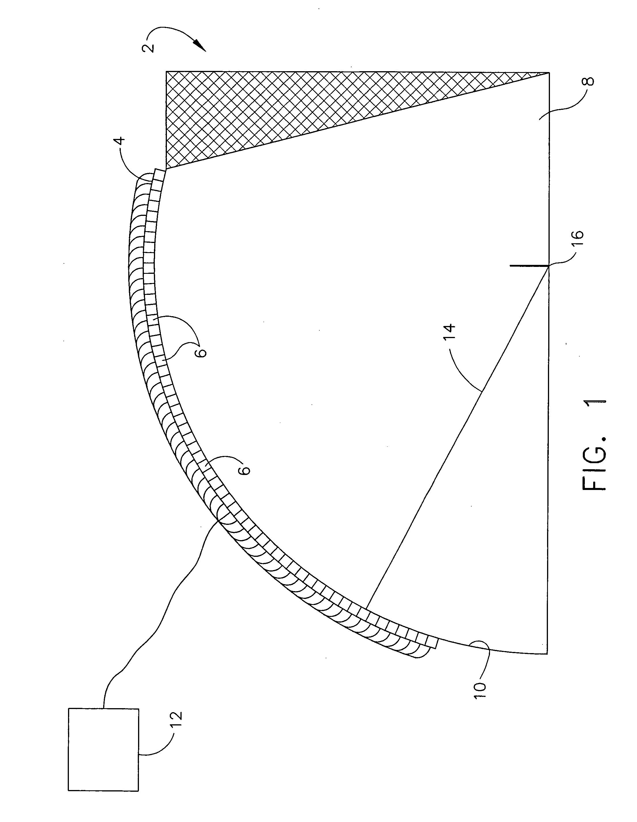
[0026] The ultrasonic probe of the present invention utilizes a delay body of having a convex outer surface, the convex outer surface having a constant radius. This probe is depicted in FIG. 1. The probe 2 includes a transducer array 4 comprising a plurality of array elements 61−n where n can be any integer. The array elements 6 are mounted on the convex outer surface 10 of the delay body 8. The delay body may be any solid material as is known in the art. Typically, delay bodies are constructed of plexiglass, polystyrene or other polymeric materials. Each transducer array element 6 in the transducer array 4 is connected to a generator 12 that provides an electrical signal which is converted by the element into a mechanical sound wave of preselected frequency as is well-known in the art. Sound waves produced by each of the transducer array elements 6 are transmitted through the delay body 8 substantially along the radius 14 from the location of the element 6x to the center 16 of the ...


PUM


Abstract

An ultrasonic probe used for inspecting a workpiece comprising a delay body and a transducer array having a plurality of transducer elements mounted on the delay body. The plurality of transducer elements of the transducer array are mounted on the curved outer surface of the delay body. The transducer elements in the array of elements are equidistant from a center of the radius of curvature of the delay body, so that sound waves simultaneously generated by two or more of the transducer elements arrive at the center of the radius, also referred to as the origin point, at the same time. For any delay body, there is a single origin point, since a curved body of constant radius can have but a single center. Since the distance from any of the transducer arrays to the index point is the same, the time delay from the index point to any of the elements is the same, so that the time delay of reflected sound passing through the index point received by a transducer in the array is not subject to a time delay resulting from the geometry of the delay body. The probe is particularly useful for inspecting work pieces that are articles of manufacture having at least one surface having a geometry that can be coupled to the workpiece.

Description

FIELD OF THE INVENTION [0001] The present invention is directed to an ultrasonic probe in the form of a transducer array, and specifically an ultrasonic probe having a probe body with a geometric shape such that transducers in the transducer array are equidistant from an origin point in the probe body so that sound waves generated simultaneously by two or more transducers in the array arrive simultaneously at the origin point. BACKGROUND OF THE INVENTION [0002] Ultrasonic probes are used for inspection of work pieces in industrial applications. The inspections have been conducted by contact methods, wherein the probe is brought into intimate contact with the workpiece, but coupled to the workpiece using a couplant such as glycerin or oil, or by non-contact or submersion methods, in which a column of water lies between the workpiece and the transducer. [0003] The probe is comprised of a delay body and at least one transducer mounted on the delay body. The at least one transducer typi...

Claims


Application Information

Patent Timeline
Patent Type & Authority Applications(United States)
IPC IPC(8): A61B6/00G01H17/00
CPCG01N29/0618G01N29/2468G01N29/262G01N2291/0421G10K11/02G01N2291/044G01N2291/106G01N2291/2632G01N2291/0422
Inventor CARODISKEY, THOMAS J.
Owner GENERAL ELECTRIC CO
Why Eureka
Try Eureka