Supercharge Your Innovation With Domain-Expert AI Agents!

Variable reluctance position sensor

a position sensor and variable technology, applied in the field of position sensors, can solve the problems of stalling, x /sub>emissions increase, and stalling, and achieve the effects of reducing noise and other anomalies, facilitating identification of portions, and promoting the flow of magnetic flux

Active Publication Date: 2007-03-29
CUMMINS INC
View PDF23 Cites 8 Cited by
  • Summary
  • Abstract
  • Description
  • Claims
  • Application Information

AI Technical Summary

Benefits of technology

The present invention provides an improved sensing apparatus and method for measuring the movement of a target along a direction of travel. The target modulates magnetic flux across a gap between a flux source and a magnetic field sensor, and the flux modulating property of the target is used to identify the position of the target. A second target with a constant flux modulating property can be used to normalize the output of the first magnetic field sensor and reduce noise. The invention has advantages over current EGR sensors and can be used in various applications.

Problems solved by technology

Where the EGR valve fails to open properly, NOx emissions increase and pre-ignition may result.
If the EGR fails to close properly, rough idling, hesitation, and stalling may occur.
Such systems are inconvenient to service.
The Hall-effect device is typically formed in silicon chips which are prone to failure at high temperatures.
However, separate mounting of the permanent magnet and Hall-effect device requires the replacement of two parts.
Furthermore, it is difficult to precisely position the permanent magnet with respect to the Hall-effect device inasmuch as they are mounted to distinct structures, one of which is movable.

Method used


Image

  • Variable reluctance position sensor
  • Variable reluctance position sensor
  • Variable reluctance position sensor

Examples


Embodiment Construction

[0032] Reference throughout this specification to “one embodiment,”“an embodiment,” or similar language means that a particular feature, structure, or characteristic described in connection with the embodiment is included in at least one embodiment of the present invention. Thus, appearances of the phrases “in one embodiment,”“in an embodiment,” and similar language throughout this specification may, but do not necessarily, all refer to the same embodiment.

[0033] Furthermore, the described features, advantages, and characteristics of the invention may be combined in any suitable manner in one or more embodiments. One skilled in the relevant art will recognize that the invention can be practiced without one or more of the specific features or advantages of a particular embodiment. In other instances, additional features and advantages may be recognized in certain embodiments that may not be present in all embodiments of the invention.

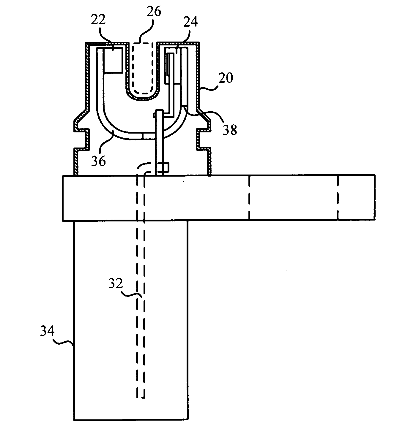
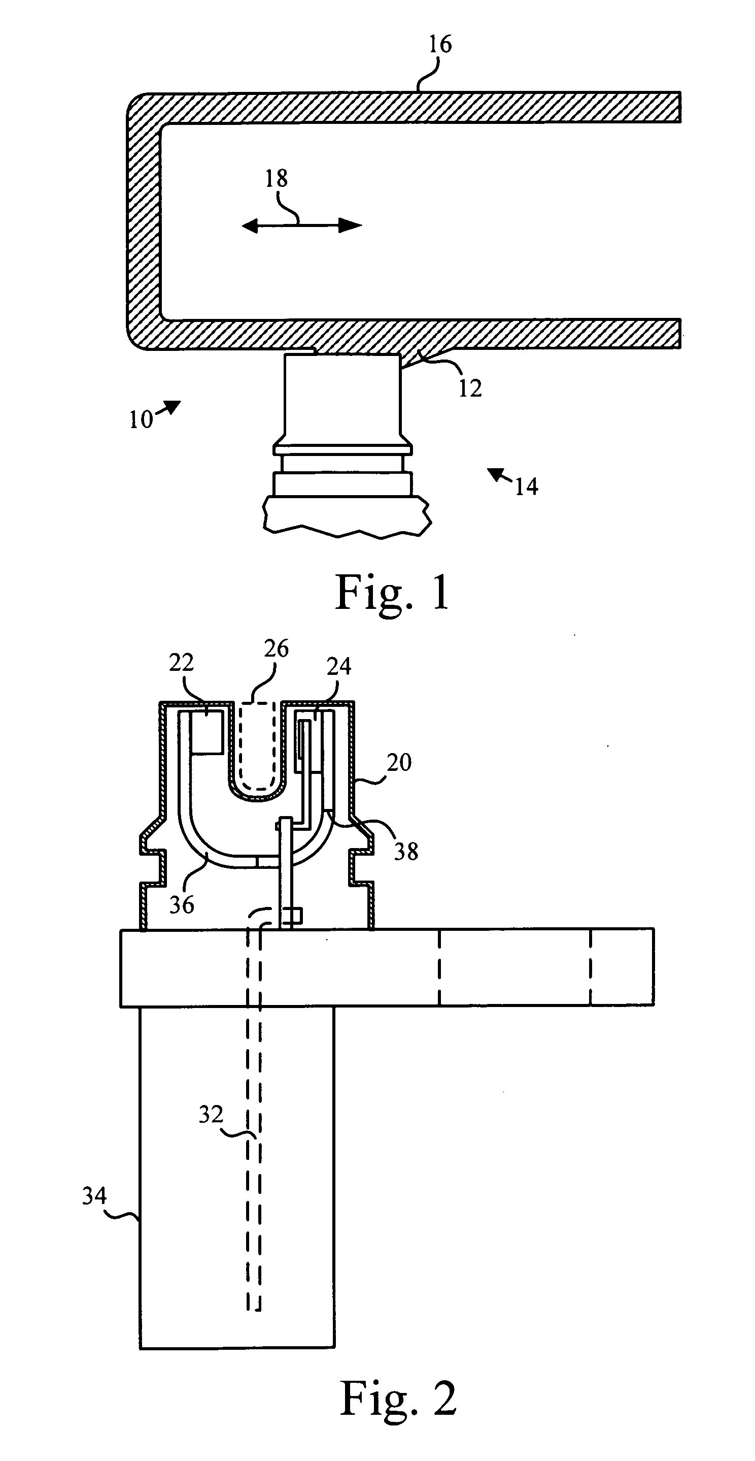
[0034] Referring to FIG. 1, a position sensor 10...


PUM


Abstract

A position sensor is disclosed having a transducer formed by a Hall-effect device and permanent magnet secured within a housing on either side of a low permeability gap. A target secured to an active member, such as an EGR valve plunger moves within the gap. The target has a flux modulating property that varies with position along a direction of travel. In one embodiment, the reluctance of the target varies with position. Variable reluctance is achieved in some embodiments by varying the cross section of the target with position. In some embodiments, a second target having substantially constant reluctance secures to the active member and moves within a gap defined by a second transducer. The output of the second transducer is used to normalize the output of the first transducer and compensate for anomalies such as drift and movement other than in the direction of travel of the active member.

Description

BACKGROUND OF THE INVENTION p 1. Field of the Invention [0001] This invention relates generally to position sensors incorporating Hall-effect devices and more particularly to systems for tracking the position of EGR valve plungers. [0002] 2. Description of the Related Art [0003] Exhaust gas recirculation (EGR) valves are used to improve the performance of automobile engines by reducing the temperature within the cylinders during combustion and by preventing pre-ignition. At high temperatures, nitrous oxides (NOx), a pollutant, tend to form. Also at high temperatures, the fuel air mixture within the cylinder tends to pre-ignite in the absence of a spark during the compression stroke, rather than during the combustion stroke. [0004] To reduce the temperature within the cylinder, the EGR valve permits small amounts of inert gas from the exhaust system to enter the cylinder during the intake stroke. The EGR valve typically has a plunger whose position determines the amount of exhaust ga...

Claims


Application Information

Patent Timeline
Patent Type & Authority Applications(United States)
IPC IPC(8): F02M25/07F02B47/08G01B7/30H01L43/06H10N50/10H10N52/00
CPCF02M25/0756F02M25/0773Y02T10/121G01D5/2013F02M25/0794F02M26/48F02M26/54F02M26/72G01D2205/775
Inventor SCHNEIDER, MATTHEW L.SCHUPPE, ALFRED
Owner CUMMINS INC
Features
  • R&D
  • Intellectual Property
  • Life Sciences
  • Materials
  • Tech Scout
  • Unparalleled Data Quality
  • Higher Quality Content
  • 60% Fewer Hallucinations
Learn More