Apparatus and methods for dispensing fluidic or viscous materials

a fluid or viscous material and apparatus technology, applied in the direction of combustion process, combustion type, burner, etc., can solve the problems of further optimization of prior art solutions in terms of cost and clean up, and achieve the effect of precise and repeatable spraying results

Inactive Publication Date: 2007-03-29
LEWIS RUSSELL H +1
View PDF40 Cites 15 Cited by
  • Summary
  • Abstract
  • Description
  • Claims
  • Application Information

AI Technical Summary

Benefits of technology

[0029] In a first aspect of the present invention, a material dispensing assembly is disclosed. In one embodiment, this apparatus contains a disposable static mixer, a disposable manifold and a disposable atomizer cap. The static mixer and the manifold have engagement features which accurately position an aperture of the atomizer cap relative to the dispensing tip of the static mixer, thereby allowing for precise and repeatable spraying results as well as the aforementioned disposability.

Problems solved by technology

Despite the foregoing broad range of solutions to deliver fluid / viscous components, all generally suffer from several salient deficiencies, including most notably the lack of a completely disposable “static mixer” or comparable mixing or dispensing assembly, and associated manifold, which are also adapted to provide consistent performance in terms of spray effluent.
In a related fashion, these prior art solutions are further not optimized in terms of cost, clean up and set up time in that (i) they are not disposable, and hence cannot be thrown away but rather must be cleaned; and (ii) they require an appreciable degree of adjustment of the components in order to produce a desired spray pattern, due in large part to the variability of the possible positions of the components of the mixer / manifold, especially in relation to one another (such as when assembled at different times by different individuals).

Method used


Image

  • Apparatus and methods for dispensing fluidic or viscous materials
  • Apparatus and methods for dispensing fluidic or viscous materials
  • Apparatus and methods for dispensing fluidic or viscous materials

Examples


Embodiment Construction

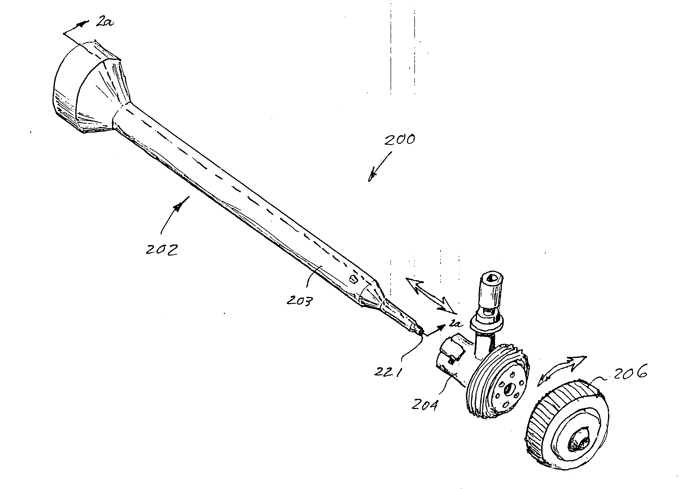
[0062] Reference is now made to the drawings wherein like numerals refer to like parts throughout.

[0063] As used herein, the term “reactive mixture” refers to any multi-component reactive mixture where each individual component, when mixed, result in a chemical reaction whereby the substantially liquid individual components harden into a substantially solid state after a relatively brief period of time. Examples of reactive components used to form a mixture include, without limitation, isocyanate and polyol, which when combined form a mixture that reacts into a substantially solid polyurethane coating.

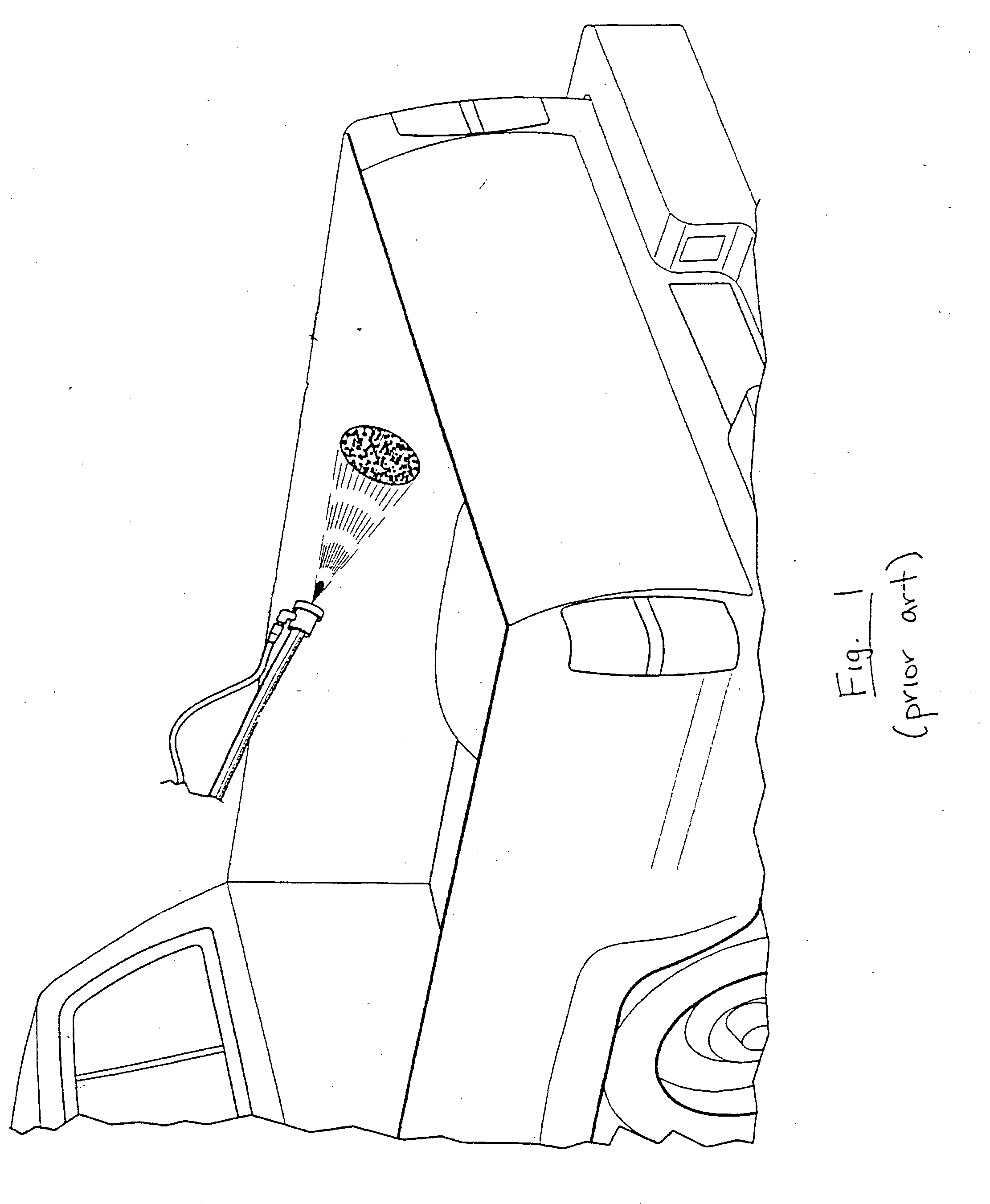
[0064] As used herein, the term “dispensing” refers to any sort of release or provision of one or more materials to a desired location. Dispensing may comprise, without limitation and for example only, spraying (atomized or airless), pouring, and spatter-coating.

Overview

[0065] In one salient aspect, the present invention provides an improved dispensing apparatus for use in, inter ...


PUM


Abstract

A dispensing apparatus and methods for use with, e.g., a multi-component reactive material process. In one embodiment, the apparatus comprises a completely disposable static mixer, manifold and atomizer cap assembly. Such a configuration allows for, inter alia, reduced cost, rapid component changes with minimal material waste, as well as reducing or eliminating the use of hazardous solvents. Precise and repeatable configuration of the dispensing assembly is also provided by way of the substantially fixed relationship of the critical components and surfaces therein.

Description

PRIORITY [0001] This application claims priority to co-pending U.S. provisional patent application Ser. No. 60 / 708,821 of the same title filed Aug. 15, 2005, incorporated herein by reference in its entirety.COPYRIGHT [0002] A portion of the disclosure of this patent document contains material that is subject to copyright protection. The copyright owner has no objection to the facsimile reproduction by anyone of the patent document or the patent disclosure, as it appears in the Patent and Trademark Office patent files or records, but otherwise reserves all copyright rights whatsoever. FIELD OF THE INVENTION [0003] The present invention relates generally to the field of plural-component coating applications, and in one exemplary aspect to apparatus and methods for delivering fluidic and / or viscous materials. DESCRIPTION OF RELATED TECHNOLOGY [0004] A variety of different techniques for delivering and / or spraying fluid and / or viscous components (such as reactive polymers used in applyi...

Claims


Application Information

Patent Timeline
Patent Type & Authority Applications(United States)
IPC IPC(8): A62C5/02B05B1/28A62C31/02F23D11/16B05B7/06
CPCA62C5/002A62C31/02B05B7/066B05B7/0408A62C31/05
Inventor LEWIS, RUSSELL H.SOLOMON, MIHAI A.
Owner LEWIS RUSSELL H
Why Eureka
Try Eureka