Input/output signals preserver circuit of amplification circuits
a technology of input/output signal and preserver circuit, which is applied in the direction of low frequency amplifiers, amplifier modifications to reduce non-linear distortion, gain control, etc., can solve the problem of inability to prevent the leakage of ac input signal vib>1, and achieve the effect of increasing the input resistance value and preventing the attenuation of input signal
- Summary
- Abstract
- Description
- Claims
- Application Information
AI Technical Summary
Benefits of technology
Problems solved by technology
Method used
Image

Examples
first embodiment
[0026] the present invention will be described with reference to the accompanying drawings.
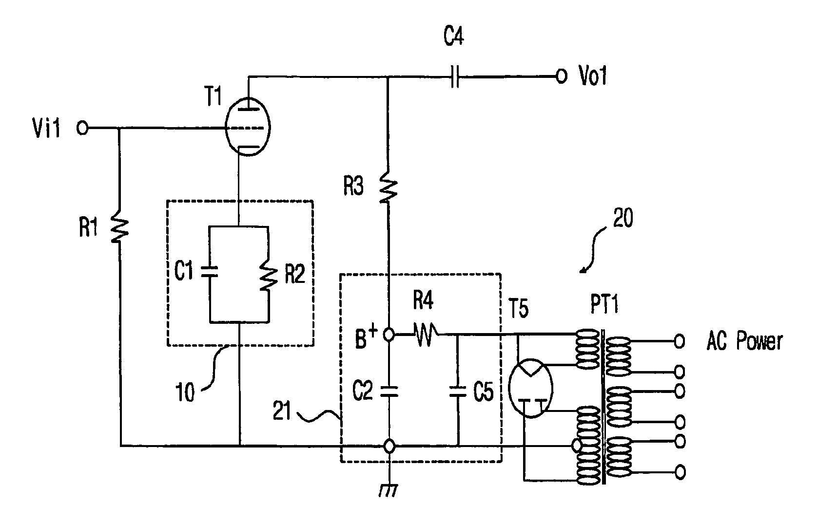
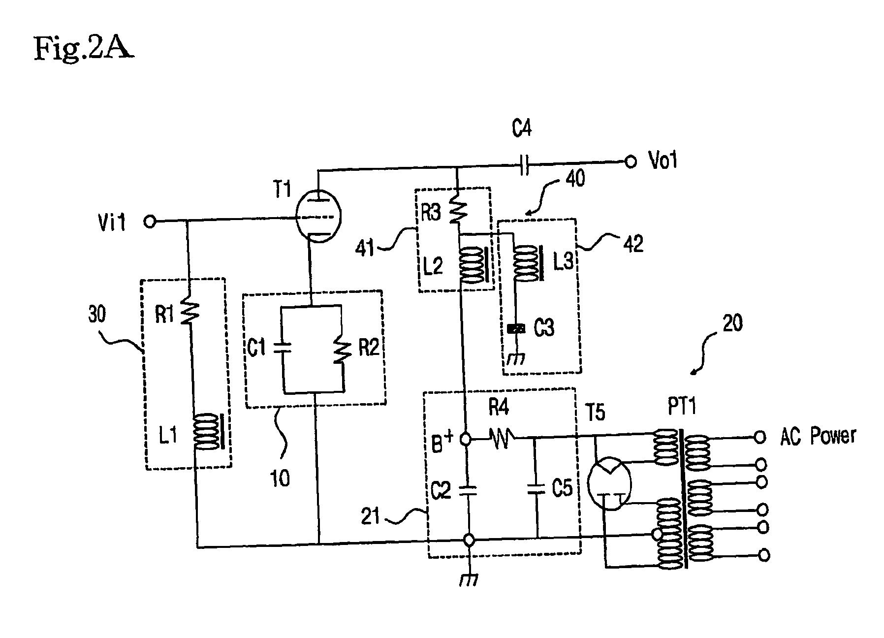
[0027]FIG. 2A is a view of a state that an input and output signal preservation circuit according to the present invention is adapted to a small signal amplification circuit of FIG. 1 adapting a vacuum tube T1 as an amplification device, wherein the vacuum tube has been used in various conventional audio systems as a pre-amplifier. Here, the vacuum tube T1 can be substituted with a transistor. The power unit 20 including the smoothing unit 21 of FIG. 1 may be directly adapted. Therefore, the same reference numerals are given, and the descriptions of the same will be omitted.
[0028] As shown in FIG. 2A, the input and output signal preservation circuit of the amplification circuit according to the present invention includes an input signal preservation unit 30 and an output signal preservation unit 40. The inventor of the present invention calls this circuit a 5A circuit or an Artist circuit and...
second embodiment
[0064] the present invention will be described with reference to FIG. 3.
[0065]FIG. 3 is a view illustrating the construction that the input and output signal preservation circuit according to the present invention is adapted to the conventional phono equalizer small signal amplification circuit for the turntable in which two vacuum tubes T6 and T7 are adapted as a two-stage amplification device. Here, the vacuum tubes T6 and T7 can be substituted with the transistors.
[0066] As shown in FIG. 3, the input and output signal preservation circuit according to the present invention includes an input signal preservation unit 50 that is formed of a bias resistor R12 and a reactor L12 and is connected with an input terminal of the first stage amplification vacuum tube T6, a voltage compensation unit 55 that is formed of a load resistor R17, a second reactor L13 and a condenser C18 and is connected with an output terminal of the first stage amplification vacuum tube T6, an input signal prese...
third embodiment
[0080] the present invention will be described with reference to the accompanying drawings.
[0081]FIG. 4 is a view illustrating the construction that the input and output signal preservation circuit according to the present invention is adapted to the conventional tape equalizer small signal ampification circuit that uses two vacuum tubes T8 and T9 as the second stage amplification device.
[0082] Here, the vacuum tubes T7 and T8 can be substituted with the transistor.
[0083] In particular, FIG. 4 is a circuit diagram illustrating the construction that the input and output signal preservation circuit according to the present invention is adapted to the conventional turntable phono-equalizer small signal amplification circuit using the second stage amplification device. There is a difference between the above embodiment and the second embodiment of FIG. 3. Namely, in this embodiment of the present invention, the time constant compensation unit 71 connected in parallel with the self-bia...
PUM
 Abstract
Description
Claims
Application Information
 - R&D Engineer
- R&D Manager
- IP Professional
- Industry Leading Data Capabilities
- Powerful AI technology
- Patent DNA Extraction
Browse by: Latest US Patents, China's latest patents, Technical Efficacy Thesaurus, Application Domain, Technology Topic.
© 2024 PatSnap. All rights reserved.Legal|Privacy policy|Modern Slavery Act Transparency Statement|Sitemap