
Transparent conductive material and transparent conductor

a technology of transparent conductive material and transparent conductive membrane, which is applied in the direction of conductive materials, non-metal conductors, carbon-silicon compound conductors, etc., can solve the problems of reduced reliability and increased electric resistance, and achieve good conductivity of the transparent conductive layer, the effect of generating a conductivity factor of oxygen vacancies and poor transparency of the transparent conductive membrane 10

Inactive Publication Date: 2009-06-04
TDK CORPARATION
View PDF19 Cites 15 Cited by
  • Summary
  • Abstract
  • Description
  • Claims
  • Application Information

AI Technical Summary

Benefits of technology

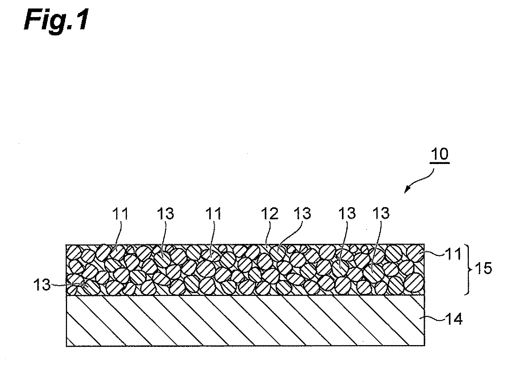
[0034]A transparent conductive layer 15 is formed of the transparent conductive material of the present invention as described hereinbelow, and stretches little even if the substrate 14 expands and therefore the resistance value hardly increases. Consequently, the substrate 14 forming the transparent conductive layer 15 is preferably composed of an organic material that hardly expands by heat or humidity, so that the advantage of the present invention can be enjoyed.
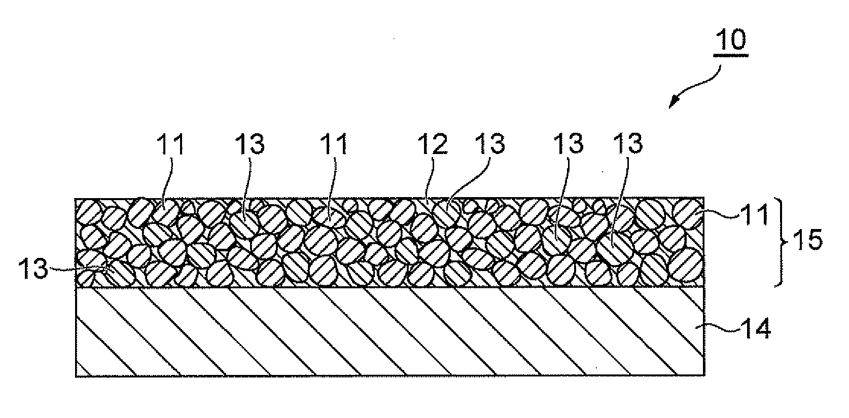
[0035]The transparent conductive layer 15 is a layer composed of a cured body of the transparent conductive material of the present invention. As shown in FIG. 1, the transparent conductive layer 15 is composed mostly of a transparent conductive particle 11 and a silica particle 13, and additionally a cured resin 12 existing in the gaps between the transparent conductive particle 11 and the silica particle 13.
[0036]The transparent conductive particle 11, the silica particle 13 and the cured resin 12 in the transparent conductive layer 15 are originated respectively from the transparent conductive particle, the silica particle or the precursor of the silica particle and the resin in the transparent conductive material. Particularly, the silica particle 13 is a silica particle itself in the transparent conductive material or a silica particle converted from a precursor of the silica particle in parallel with curing of the transparent conductive material. The cured resin 12 is formed by curing the resin in the transparent conductive material with heat or a high energy electromagnetic wave such as light and an electron beam.
[0037]The particle size of a primary particle of the transparent conductive particle 11 in the transparent conductive layer 15 is preferably 0.005 to 0.5 μm, and more preferably 0.01 to 0.08 μm. In case the particle size of the primary particle of the transparent conductive particle 11 is less than the above range, generation of a conductivity factor of oxygen vacancies tends to become more difficult than that of inside the range and the good conductivity of the transparent conductive layer 15 cannot be obtained stably. In contrast, in case the particle size of the primary particle is too large, the light scattering becomes stronger than that of inside the range and the transparency of the transparent conductive membrane 10 may become poorer. To realize such primary particle size of the transparent conductive particle 11, the transparent conductive particle to be contained in the transparent conductive material should have such primary particle size.
[0038]The particle size of a primary particle of the silica particle 13 is preferably 0.005 to 0.5 μm, and more preferably 0.005 to 0.05 μm. In case the particle size of the primary particle of the silica particle is too small, the adhesion of the silica particle 13 to the surface of the transparent conductive particle 11 becomes remarkably large and direct contacts among the transparent conductive particles 11 decrease, which may lead to decrease in the conductivity. In case the particle size is too large, the transparent conductive particles 11 tend to be placed in the gaps among the silica particles 13, so that the contacts between the transparent conductive particles 11 decrease, and the light scattering in the transparent conductive layer 15 increases to decrease the transparency. To make the primary particle size of the silica particle 13 within such range, the silica particle in the transparent conductive material should have such primary particle size or the content of the precursor of the silica particle should be adjusted, so that such primary particle size can be obtained.
[0039]The cured resin 12 is placed in the gaps among the transparent conductive particles 11 and the silica particles 13 and functions to bond the particles together. Thereby, although not illustrated, the cured resin 12 and the transparent conductive particle 11 or the silica particle 13 are quasi bonded by a structure derived from a silane coupling agent contained in the transparent conductive material.

Problems solved by technology

However, conventional transparent ITO electrodes obtained by the coating method has tendency that, when placed in a high temperature and / or high humidity environment, the electric resistance is increased by oxygen or moisture in the atmosphere, which is a cause of reduced reliability.

Method used


Image

  • Transparent conductive material and transparent conductor
  • Transparent conductive material and transparent conductor
  • Transparent conductive material and transparent conductor

Examples


examples

[0054]The present invention will now be described in more detail by way of Examples thereof but the present invention is not limited thereto.

examples 1 to 10

, Comparative Examples 1 to 3

[0055]As the components of the transparent conductive material, ITO particles for the transparent conductive particle, a silica particle for the silica material, an acrylic resin for the resin, and vinyltrimethoxysilane (KBM1003 from Shin-Etsu Chemical Co., Ltd.) for the silane coupling agent were used respectively to produce according to the following production method transparent conductive membranes of Examples 1 to 10 and Comparative Examples 1 to 3 provided with transparent conductive layers formed from the transparent conductive materials respectively.

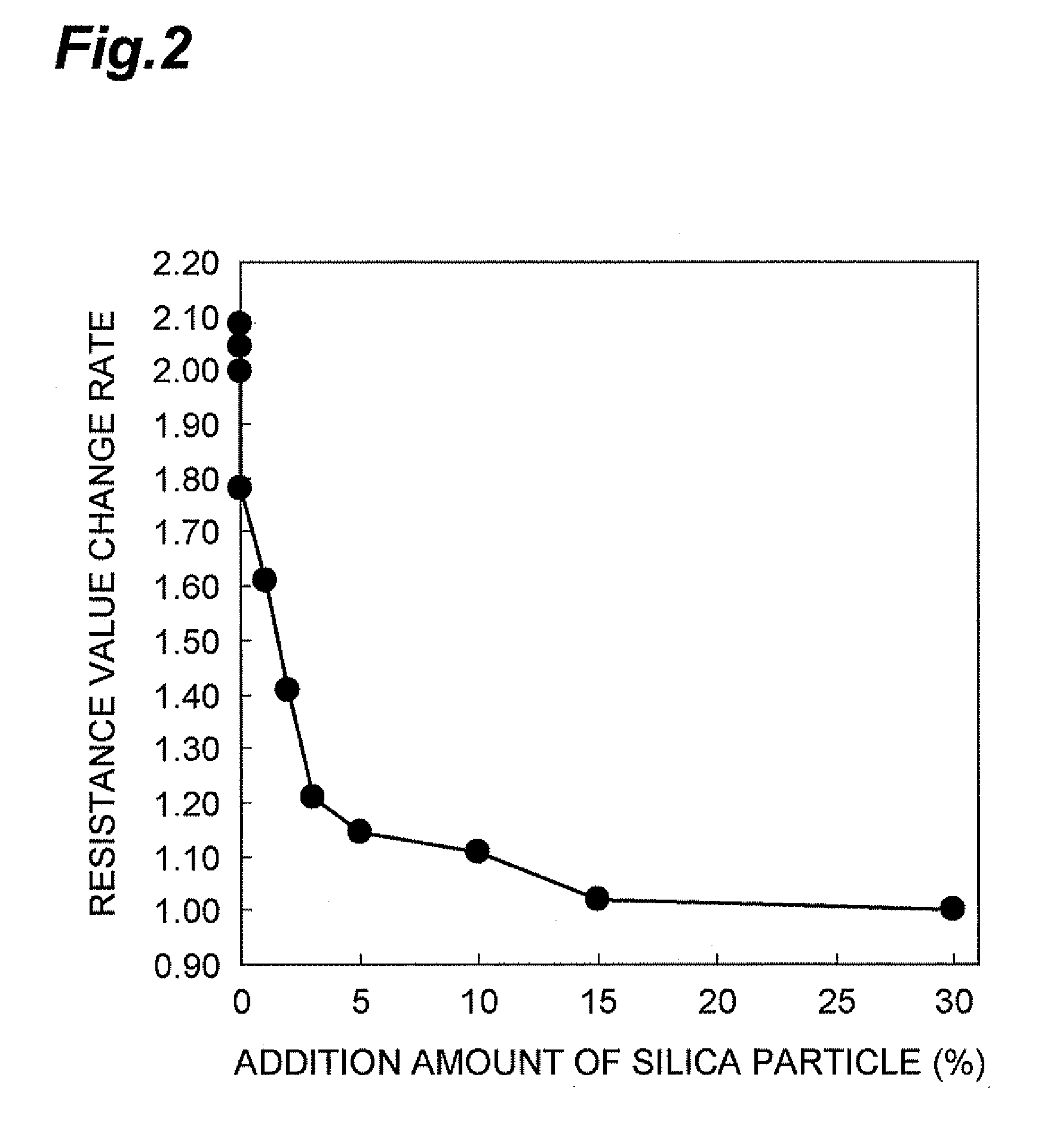
[0056]The percentage of the silica particle, and the presence or absence of the addition of the silane coupling agent were changed among Examples 1 to 10 and Comparative Examples 1 to 3 respectively as shown in Table 1 below. In Table 1 “No” or “0” (%) means that the relevant component was not used, and in the following production method, a transparent conductive membrane was produced without adding t...


PUM


Abstract

The present invention provides a transparent conductive material with little change in electric resistance under influence of temperature or humidity and a transparent conductive membrane using the same.The transparent conductive material of the present invention includes a resin, a transparent conductive particle, a silica material containing at least either of a silica particle or a precursor of silica particle, and a silane coupling agent.

Description

BACKGROUND OF THE INVENTION[0001]1. Field of the Invention[0002]The present invention relates to a transparent conductive material and a transparent conductor using the same.[0003]2. Related Background Art[0004]A transparent electrode is used for a display device, such as an LCD, a PDP, an organic EL and a touch panel. The transparent electrode is often constituted of a transparent conductive material such as indium tin oxide (hereinafter abbreviated as “ITO”). An ITO electrode formed by sputtering deposition has been used as the transparent electrode. Meanwhile, a coating method to prepare an ITO electrode has also drawn attention, because it can impart a property such as high flexibility not attainable by an ITO electrode obtained by a sputtering method. However, conventional transparent ITO electrodes obtained by the coating method has tendency that, when placed in a high temperature and / or high humidity environment, the electric resistance is increased by oxygen or moisture in t...

Claims


Application Information

Patent Timeline
IPC IPC(8): H01B1/22
CPCH01B1/22H01B1/16
Inventor INABA, KAZUHISAYASUDA, NORIYUKI
Owner TDK CORPARATION
Learn More