Antenna system for a radiocommunication station, and radiocommunication station having such antenna system

Inactive Publication Date: 2007-03-29
NORTEL NETWORKS LTD +1
View PDF5 Cites 7 Cited by
  • Summary
  • Abstract
  • Description
  • Claims
  • Application Information

AI Technical Summary

Benefits of technology

[0009] An object of the present invention is to provide an antenna system which makes it poss

Problems solved by technology

In a handheld terminal, it is not easy to ensure spatial decorrelation of the antenna elements because the dimensions are sma

Method used


Image

  • Antenna system for a radiocommunication station, and radiocommunication station having such antenna system
  • Antenna system for a radiocommunication station, and radiocommunication station having such antenna system
  • Antenna system for a radiocommunication station, and radiocommunication station having such antenna system

Examples


Embodiment Construction

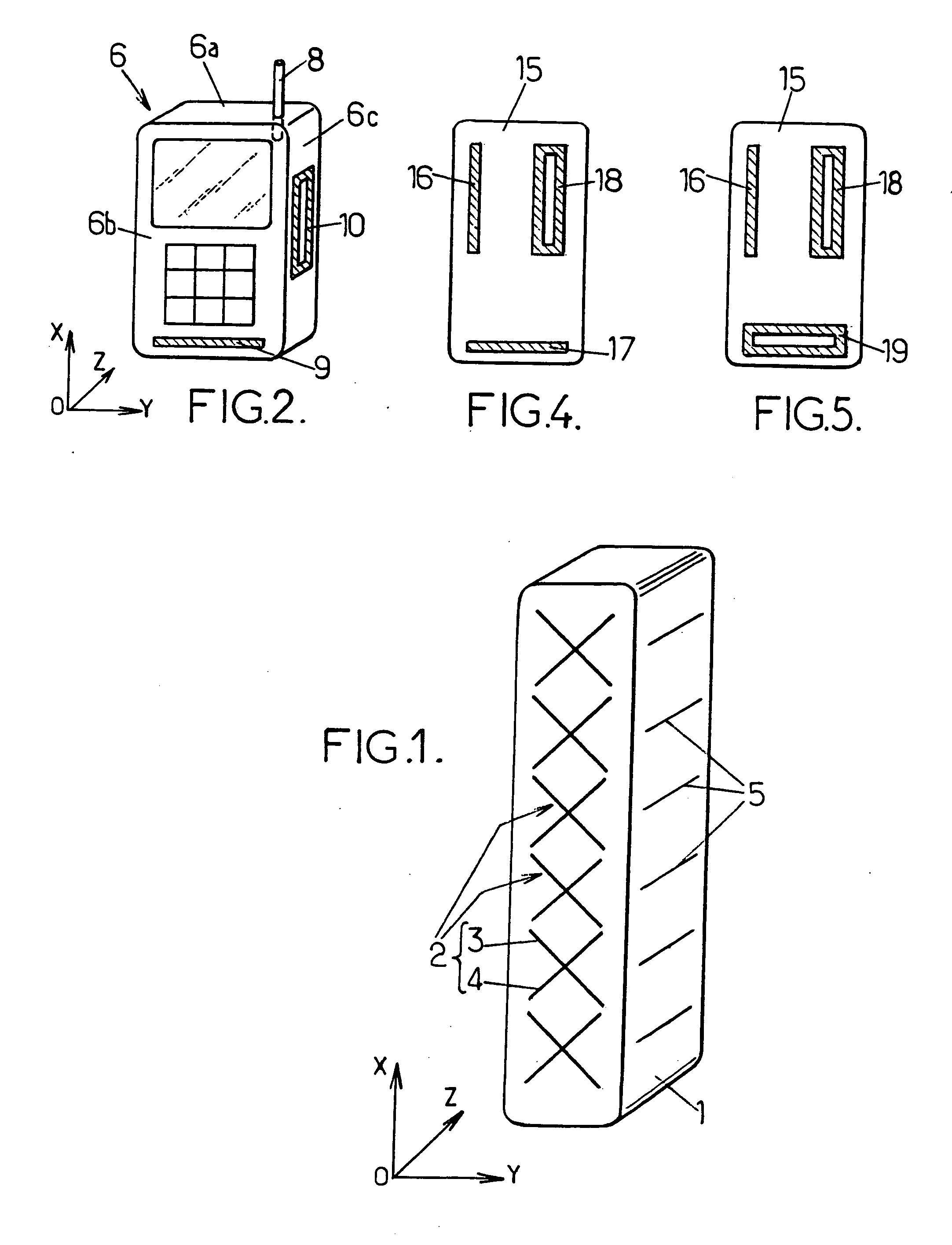
[0020]FIG. 1 shows an aerial array for a base station of a cellular radiocommunication network. In a conventional manner, it has a facet 1 oriented towards the cell to be served by the station, with a number of antenna elements 2 arrayed on the facet. In the illustrated example, the antenna elements are cross-polarization elements 2, each consisting of two dipoles 3, 4 having a mutual angle of 90°. They are thus arranged to transmit (or to be sensitive to) electromagnetic waves having their electric field parallel to the plane xOy the facet 1. The dimensions of the dipole elements 3, 4 are of the order of half of the wavelength used in the communication system. They are arrayed and fed with suitable phase shifts so as to provide the desired directivity in the elevation plane xOz.

[0021] In accordance with the invention, additional antenna elements 5 are provided in the aerial array, in order to interact with electromagnetic waves having their electric field perpendicular to the face...


PUM


Abstract

The antenna system for a radiocommunication station has a plurality of antenna elements having different polarizations and arranged for coupling with RF electric field components oriented along three mutually perpendicular directions.

Description

FIELD OF THE INVENTION [0001] The present invention relates to antenna systems for radiocommunication stations. BACKGROUND OF THE INVENTION [0002] Most radiocommunication stations use dipoles as antenna elements. The dipole is sensitive to RF electromagnetic waves having the electric field parallel to the direction of the dipole. [0003] It is known to arrange dipoles having two different orientations so that the station can transmit or receive radio waves having different polarizations of the electric field E. In the “cross-polarization” arrangement two dipoles are disposed at right angles in a common plane. This makes the antenna sensitive to both the horizontal and the vertical polarization of the electric field E, or to a circular polarization if used with suitable RF couplers (see WO 97 / 37440). [0004] Another common type of antenna element consists of a slot cut in a metallic plane and fed across the two lateral edges of the slot. The slot antenna has a radiation diagram dual of...

Claims


Application Information

Patent Timeline
IPC IPC(8): H01Q1/24
CPCH01Q1/242H01Q9/16H04B7/10H01Q21/24H01Q21/29H01Q13/10
Inventor LUCIDARME, THIERRYRACHED, NIDHAM BEN
Owner NORTEL NETWORKS LTD
Why Eureka
Try Eureka