Thermal printer and method for operating same

Active Publication Date: 2007-03-29
KODAK ALARIS INC
View PDF6 Cites 107 Cited by
  • Summary
  • Abstract
  • Description
  • Claims
  • Application Information

AI Technical Summary

Benefits of technology

[0007] In one aspect of the invention, a thermal printer is provided. The thermal printer comprises a donor transport system having a motorized system for advancing a donor web relative to a printhead, the donor web having patches of donor material including at least one colored donor material; a receiver transport system having a motorized system for advancing a receiver web relative to the printhead; the printhead being able to actuate heat and transfer donor material from the donor web to the receiver web; a first thermal sensor adapted to sense thermal energy indicative of the temperature of the printhead and to generate a primary thermal feedback signal representative of the temperature of the printhead; a controller for controlling the operation of the donor transport system, the receiver transport system, and the printhead so as to enable imagewise transfer of donor material onto the receiver web to form a sequence of at least two images, the controller being operable to interpose at least one programmed delay between the printing of at least two of the images in the sequence; wherein the controller determines the length of each programmed delay by using the temperature of the thermal printhead and a time rate of cooling of the printhead in a manner that is adapted to provide a sufficient cooling time to prevent the printhead from reaching a maximum printhead temperature during printing of the sequence of images.
[0008] In another aspect of the invention, a method is provided for operating a printing system which applies donor material from donor patches on a donor web to a receiver medium using a thermal printhead that generates heat. In this aspect, the method

Problems solved by technology

These increased temperatures can neg

Method used


Image

  • Thermal printer and method for operating same
  • Thermal printer and method for operating same
  • Thermal printer and method for operating same

Examples


Embodiment Construction

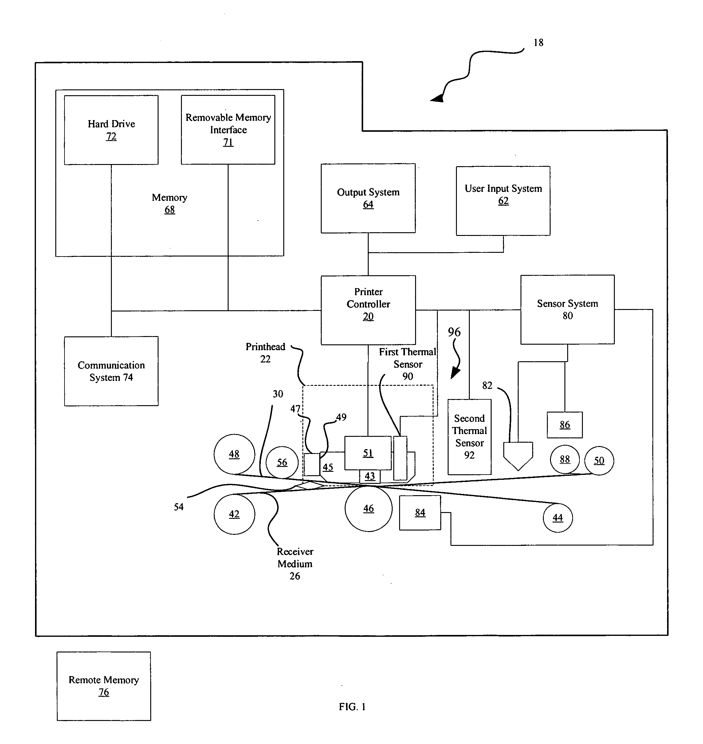
[0016]FIG. 1 shows one embodiment a printer 18 of the invention. As shown in FIG. 1, printer 18 has a controller 20 that causes printhead 22 to record images on a receiver medium 26 by applying heat and pressure to transfer material from a donor web 30 to receiver medium 26. Controller 20 can include but is not limited to a programmable digital computer, a programmable microprocessor, a programmable logic controller, a series of electronic circuits, a series of electronic circuits reduced to the form of an integrated circuit, or a series of discrete components. In the embodiment of FIG. 1, controller 20 also controls a receiver medium take-up roller 42, a receiver medium supply roller 44, a donor web take-up roller 48 and a donor web supply roller 50, which are each motorized for rotation on command of the controller 20 to effect movement of receiver medium 26 and donor web 30.

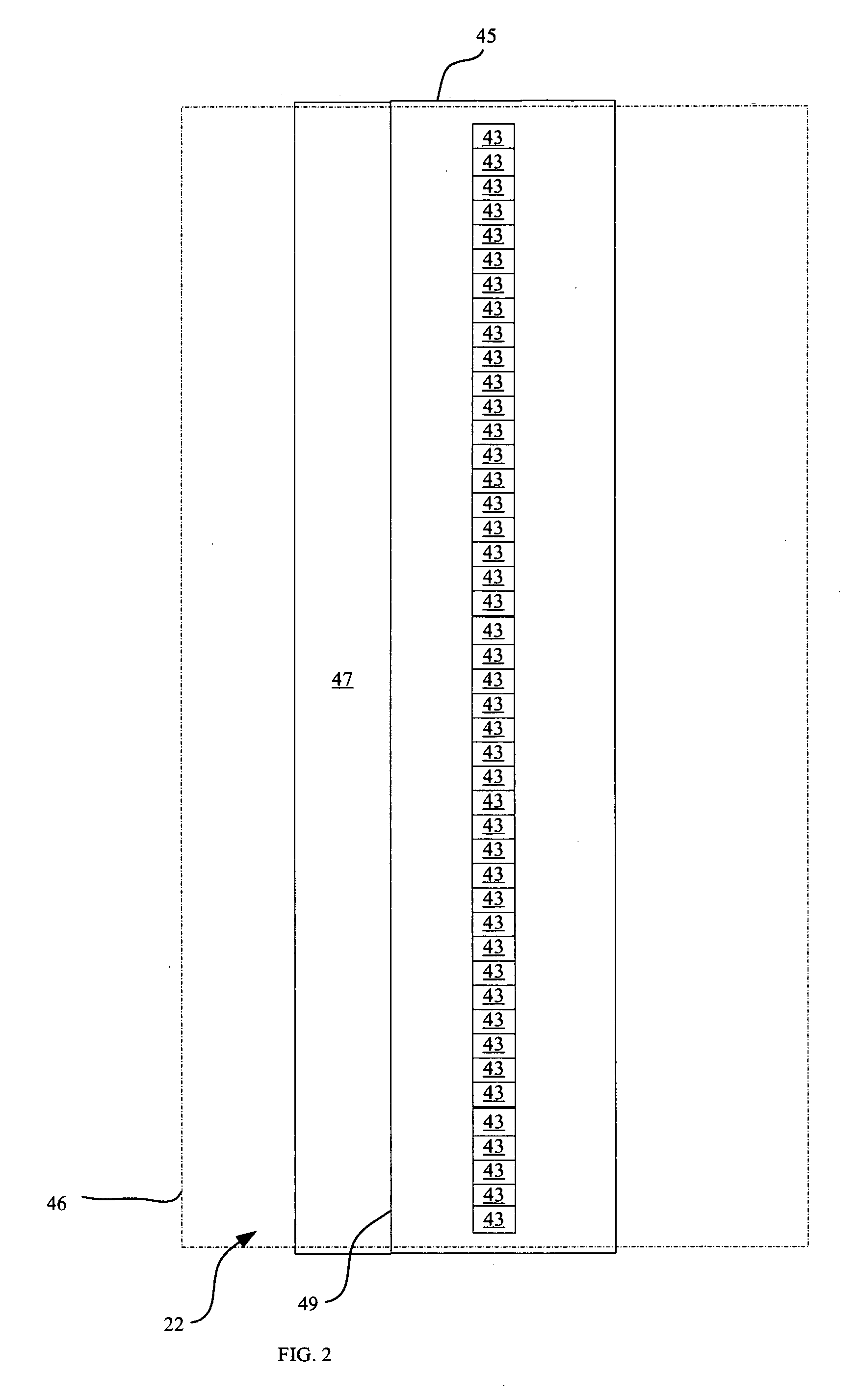
[0017]FIG. 2 shows a bottom view of a illustration of one embodiment of a conventional thermal printhead 2...


PUM


Abstract

A printer that applies donor material from donor patches on a donor web to a receiver medium using a thermal printhead that generates heat and a method for operating such a printer are provided. The method comprises the steps of: receiving a print order requesting the printing of a quantity of images; determining a temperature of the printhead; printing a designated number of the quantity of the images in a sequence; determining a length of time of a programmed delay; delaying the printing for the determined length of time of the programmed delay; and printing remaining images from the quantity of images. The length of each programmed delay is determined by using the temperature of the printhead and a time rate of cooling of the printhead and, is determined in a manner that provides a sufficient cooling time to prevent the printhead from reaching a maximum printhead temperature during printing.

Description

FIELD OF THE INVENTION [0001] The present invention relates to thermal printers of type that apply material from a donor web to a receiver web in order to form images on the receiver web. BACKGROUND OF THE INVENTION [0002] In thermal printing, it is generally well known to render images by heating and pressing one or more donor materials such as a dye, colorant or other coating against a receiver medium. The donor materials are provided in sized donor patches on a movable web known as a donor ribbon. The donor patches are organized on the ribbon into donor sets, each set containing all of the donor patches that are to be used to record an image on the receiver medium. For full color images, multiple color dye patches can be used, such as yellow, magenta and cyan donor dye patches. Arrangements of other color patches can be used in like fashion within a donor set. Additionally, each donor set can include an overcoat or sealant layer. [0003] Thermal printers offer a wide range of adva...

Claims


Application Information

Patent Timeline
IPC IPC(8): B41J2/36
CPCB41J2/375
Inventor MINDLER, ROBERT F.CAHOON, ROBERT C.
Owner KODAK ALARIS INC
Why Eureka
Try Eureka