Backlight assembly and liquid crystal display module using the same

Active Publication Date: 2007-03-29
LG DISPLAY CO LTD
View PDF9 Cites 140 Cited by
  • Summary
  • Abstract
  • Description
  • Claims
  • Application Information

AI Technical Summary

Benefits of technology

[0016] An object of the present invention is to provide a backlight assembly that can provide high brightness.
[0017] An object of the present invention is to provide a backlight assembly that can provide high contrast.
[0018] An object of

Problems solved by technology

However, the increased number of LEDs increases the cost and power consumption of a backlight unit.
Thus, it is difficult to obtain a high contrast due to weak brightness in a space between

Method used


Image

  • Backlight assembly and liquid crystal display module using the same
  • Backlight assembly and liquid crystal display module using the same
  • Backlight assembly and liquid crystal display module using the same

Examples


Embodiment Construction

[0034] Reference will now be made in detail to the preferred embodiments of the present invention, examples of which are illustrated in the accompanying drawings.

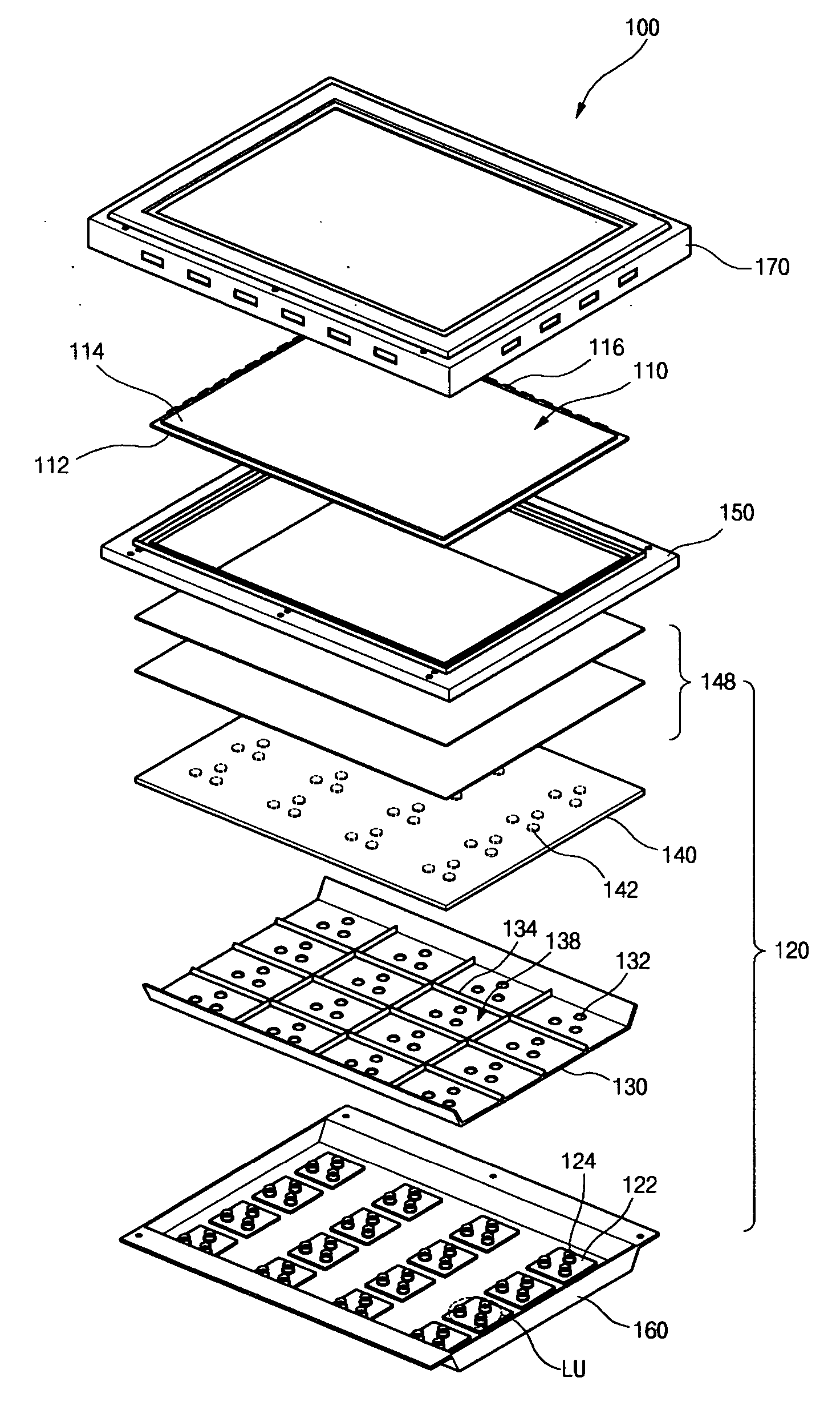
[0035]FIG. 3 is an assembly view of an LCD module using a backlight assembly according to an embodiment of the present invention. As shown in FIG. 3, an LCD module 100 includes a liquid crystal panel 110 and a backlight assembly 120 under the liquid crystal panel 110. A main frame 150 surrounds edges of the liquid crystal panel 110 and the backlight assembly 120. For example, the main frame 150 can be a stainless use steel (SUS) or plastic mold member. A bottom frame 160 covers a backside of the backlight assembly 120. Further, a top frame 170 surrounds a front edge of the liquid crystal panel 110 and attaches to the bottom frame 160 through the main frame 150. Together, the top frame 170, the main frame 150 and the bottom frame 160 minimize light loss and maintain the shape of the LCD module 100.

[0036] The liquid crystal...


PUM


Abstract

A backlight assembly includes light emitting diodes in patterns, a reflective sheet having a plurality of through holes through which the light emitting diodes protrude, and a sidewall dividing the patterns into a plurality of light emitting diode units.

Description

[0001] The present invention claims the benefit of Korean Patent Application No. P2005-0131721, filed in Korea on Dec. 28, 2005, which is hereby incorporated by reference in its entirety. BACKGROUND OF THE INVENTION [0002] 1. Field of The Invention [0003] The present invention relates to a light source, and more particularly, a backlight assembly including a plurality of light emitting diodes (LEDs) and a liquid crystal display (LCD) module using the backlight assembly. [0004] 2. Discussion of The Related Art [0005] Flat panel display (FPD) devices that have relatively light weight, thin profile, and low power consumption characteristics are being commonly used as a substitute for cathode ray tube (CRT) devices. Generally, display devices may be classified according to their ability for self-emission, and may include emissive display devices and non-emissive display devices. Emissive display devices display images by self-emitting light, while the non-emissive display devices requir...

Claims


Application Information

Patent Timeline
IPC IPC(8): F21V7/00H01L33/60
CPCG02F1/133603G02F1/133605Y10S362/80G02F1/133611G02F1/133609G02F1/1335
Inventor BANG, JU-YOUNG
Owner LG DISPLAY CO LTD
Why Eureka
Try Eureka